 |
|
 05-08-2020, 08:38 AM
|
#41
|
|
Moderator
Join Date: Nov 2006
Location: Ohio
Posts: 12,656
SUN #89
|
Glad you made it back home safe and sound. So sorry to hear about your brother. We know the effects of cancer all to well. We will pray for your family in yoru time of need.
Ah yup, with frost and mix precipitation in early May, your right, the heat went somewhere else....
__________________
__________________
Current Sunlines: 2004 T310SR, 2004 T1950, 2004 T2475, 2007 T2499, 2004 T317SR
Prior Sunlines: 2004 T2499 - Fern Blue
2005 Ford F350 Lariat, 6.8L V10 W/ 4.10 rear axle, CC, Short Bed, SRW. Reese HP trunnion bar hitch W/ HP DC
 Google Custom Search For Sunline Owners Club
|

|

|
|
05-10-2020, 04:05 PM
|
#42
|
|
Senior Member
Join Date: Jan 2020
Location: Maryland
Posts: 143
SUN #11755
|
Been picking at the inverter since friday and not much progress until today.
It's mounted in the side compartment under the bed.
12V has been redone with 8ga from the power panel to the cut off switch (which isn't mounted yet, although it's wired.)
Tied in the Inverter to the 12V at the New 30A breaker (panel side). The Old inverter was disconnected completely from the panel. New cable run to the Cut off switch.
All grounds redone with new connectors and dremeled frame section, new self tapping screws, and sprayed with Battery Terminal protector spray. All 12V grounds underneath bonded together with 12GA Bare wire.
New 120V line run underneath using existing access holes in floor (VERY TIGHT FITTING!), new box, outlet, and connections in the panel. Grounds between outlet box and Inverter box bonded.
Trailer Jack connected 12V downside of switch. Ground to bonded grounds. Works very well!
Brought it up on battery(no shore power) with all 120V disconnected from shore power. No SMOKE or loads with everything off. Battery Voltage 12.2V (It's been sitting disconnected for 7 weeks). Turned on lights (about 1/2 of them and let them run 5 minutes while checking for connections heating. NOTHING. All Good!
Connected shore power. Brought the mains online. No Smoke. Brought the other 5 breaker on 1 minute apart (check amps on shore line.) Still No SMOKE (I must have screwed up and done it right  !). As everything was off the only load was the inverter and that drew just under 2.0A with just the battery charging. Quick check showed 13.78V on charge (it's working! YEA!) (I had my Variac connected on the shore line (it has a 3A and 15A meters)
All I have to do now is drill the 1" hole in the cross member for the cut off switch, and wiretie everything up and out of the way.
Larry
Clipboard01.jpg
__________________
|
|
|
|
|
05-10-2020, 09:09 PM
|
#43
|
|
Moderator
Join Date: Nov 2006
Location: Ohio
Posts: 12,656
SUN #89
|
You will really like the PD power converter. I have yet to even hear the fans run on mine. They are variable speed and proportional to the amount of heat or power the system is creating. The heat sink is so big convecting off heat and, it may be my power needs are that small since converting to LED lights, I do not hear the fans as they are not running.
Do you have a DC amp meter to measure the amount of amps the PD converter will put in the battery? Curious with your new location setup and wiring, how much the PD will recognize and pump into the battery bank. You may need to discharge the battery down to the 50 to 60% charged area to find out what max it will put into the battery.
John
__________________
Current Sunlines: 2004 T310SR, 2004 T1950, 2004 T2475, 2007 T2499, 2004 T317SR
Prior Sunlines: 2004 T2499 - Fern Blue
2005 Ford F350 Lariat, 6.8L V10 W/ 4.10 rear axle, CC, Short Bed, SRW. Reese HP trunnion bar hitch W/ HP DC
Google Custom Search For Sunline Owners Club
|
|
|
|
|
05-10-2020, 09:35 PM
|
#44
|
|
Moderator
Join Date: Nov 2006
Location: Ohio
Posts: 12,656
SUN #89
|
Hi Larry,
I "thought" I saw something mixed up in your pic, but maybe not and most likely not.
I saw you using a white wire out of the converter to the self resetting circuit breaker which would indicate the positive terminal out of the PD unit. And I saw a black leaving the converter to head somewhere we cannot see.
The lettering in the pic is too small to read, but I think I figured it out. Are you using white as the positive out the PD converter and black as the DC common? Is that what we are seeing?
That is what threw me at first glance as Sunline used white as DC common and red or black as DC positive. The wire itself does not matter, the color of the insulation is the only difference.
Looking where the PD has the positive hot terminal, which I think is more in the center of the PD unit, you have the white wire in that location.
See mine. The Blue strip is positive at the center of the converter, the yellow is negative near the edge of the converter.

At the fuse panel of the old power converter case

Your setup looks nice and clean and good air flow. Maybe a thought to consider, add a wood or plastic cover over the self resetting terminals in case someone ever puts something metal by accident in that storage area. A large frying pan/griddle or cookie sheet etc. The case on the converter is common to DC negative and a metal object touching both will trip the fuses.
Thanks for sharing
John
__________________
Current Sunlines: 2004 T310SR, 2004 T1950, 2004 T2475, 2007 T2499, 2004 T317SR
Prior Sunlines: 2004 T2499 - Fern Blue
2005 Ford F350 Lariat, 6.8L V10 W/ 4.10 rear axle, CC, Short Bed, SRW. Reese HP trunnion bar hitch W/ HP DC
Google Custom Search For Sunline Owners Club
|
|
|
|
|
05-12-2020, 08:34 PM
|
#45
|
|
Senior Member
Join Date: Jan 2020
Location: Maryland
Posts: 143
SUN #11755
|
Yeah I used a piece of White 8ga for B+ out of the converter to the breaker. The red on that side goes to the power panel. The other side of the breaker to the switch, then to battery. The black goes thru the floor and about 4" to chassis ground. I checked the temp on the converter and it's barely Lukewarm. I haven't attached the pendant yet. (my 14 year old Troybilt rider blade spindles seized, so broke down and bought a new cub cadet rider. Troybilt Rider gets blade deck ectomy and now pulls the yard cart.) Spent all day mowing and getting the new mower.). Gotta clean out the garage tomorrow, so good time to test the Battery(no shore power) with all the lights on for 6-8 hours or so, then fire up the shore power and see how it does.
The red to the power panel from the breaker goes to the upper connection (old battery connection,then to the 2-30 amp fuses then gets distributed as built. The old converter B+ connection (bypassing the fuses) is NOT connected, so all power from the battery goes 1st thru the breaker and then thru the fuses. The converter power (B+) is tied in at the breaker on the panel side of the breaker, and on to the panel via the battery lead. So now the converter B+ is also fused on both legs of the fuse panel. Electrically the same but differently set up. Everything now is fused at the panel where before the only fuse for the converter was on the circuit board for input power. I know, it's overkill (fusing), but I hate fires too.
I'll try and get some pics of the grounds/switch/inside of panel tomorrow or thursday.
This is final layout.

__________________
|
|
|
|
|
05-13-2020, 08:37 PM
|
#46
|
|
Senior Member
Join Date: Jan 2020
Location: Maryland
Posts: 143
SUN #11755
|
In Your last post you stated the case is common with DC NEGATIVE? Metered out to ZERO VOLTS DC BETWEEN CASE and 12V DC. It does show continuity from the CORD GROUND LEAD. So it's common with AC GROUND LEAD. NO CONTINUITY on my case to DC NEGATIVE TERMINAL. In any case I double checked before powering up the isolation of the DC circuits from the AC Supply.
I was planning on running the lights for a few hours, but life got in the way, and after 9 hours the lights were dead. Plugged in shore power and turned off lights. Checked voltage at battery prior to plug in about 7.5V. 10 min after plug in 12.65 and climbing slowly. 30 min 13.12vdc. At that point I found the pendant while looking for something else. Plugged it in and set for boost mode. That was about 7:30pm and Voltage was up to 13.56VDC. I haven't checked it since,(I'll do that in morning.) NOTE: at the 30 minute mark the Fans were on, on the Converter, and the heatsinks were HOT! Sucker puts out almost as much heat as one of my tube receivers. Last thing to do before Md. State Safety Inspection is to swap tires with the '94 Innsbruck (1 yr old goodyears). Anyway here's some pics.
Tongue with NEW Electric Jack. 7way plug. New 7Way jack mounted to battery mount Rails & wired to Cutout switch. Also can connect to Truck. I haven't put anything away or trashed yet, so don't mind the mess.

Shows 7Way Jack, with plug from jack inserted, and New Cutout Switch.

Shows back side of Cutout switch and partial of new wiring. Romex type is from Trailer Jack plug.

Shows all grounds, and new wiring. Ground lugs all bonded together to ensure good grounding and alleviate ground loops.

__________________
|
|
|
|
|
05-16-2020, 07:15 AM
|
#47
|
|
Moderator
Join Date: Nov 2006
Location: Ohio
Posts: 12,656
SUN #89
|
Quote:
Originally Posted by Torskdoc423

In Your last post you stated the case is common with DC NEGATIVE? Metered out to ZERO VOLTS DC BETWEEN CASE and 12V DC. It does show continuity from the CORD GROUND LEAD. So it's common with AC GROUND LEAD. NO CONTINUITY on my case to DC NEGATIVE TERMINAL. In any case I double checked before powering up the isolation of the DC circuits from the AC Supply.
|
H'mm, OK something not adding up or I miss read your wording. OR you are missing a grounding wire. Read on.
On the camper, earth ground (shore line cord earth ground and AC ground the same thing) should be common to DC negative (camper frame ground). This may be where you have an issue.
All the metal frame, siding etc on the camper, should be common to the incoming earth ground in the power cord. And it should be common to your battery DC negative. This pic shows your DC negative on your camper, "assuming" the heavy white wire is going to the gas pipe is the DC negative off the battery. Is it?
The AC world earth ground and the DC world negative of the camper are common to each other and should have continuity between them, but it stops there. The AC neutral should "not" be common to DC negative or AC earth ground on the camper. Single point grounding rules are that AC neutral and earth ground are only common in one spot at the main AC power entrance panel. The camper is considered an appliance to the AC system it is plugged into.
I think you agree with all that, don't you?
Now to the case on the outside of the PD converter, I see you have the extra bare copper wire to outside of the metal outlet box, and the metal outlet box should have a ground on it from the 120 VAC power cord, The PD converter inside should also have the power cord earth ground connected to the case

BUT, that case ground is on wood even though it would be connected to the outlet box AC ground from the 120 VAC cordset.
But then you said this, I highlighted in blue above which is where I'm not following what you indicated, again if I read it correct.
Quote:
|
So it's common with AC GROUND LEAD. NO CONTINUITY on my case to DC NEGATIVE TERMINAL.
|
Not sure how there is no continuity between your PD case and the DC negative terminal on the battery then, if that was where you where testing it, unless the battery disconnect switch was off and installed in the DC negative line. But, the back of your disconnect switch you added has the large red wire which would be DC positive. So, I'm not sure how the PD case and DC negative are not getting a continuity check to work.
OK thinking through this, I think you are missing the one place the AC world in the camper connects the incoming shore line cord earth ground to the DC frame ground (DC negative).
Follow the incoming shore line cord to where it comes into the camper. It should be by the old location of the power converter. The white AC neutrals from AC outlets in the camper are on their own buss bar and isolated from earth ground. Then, the 120 VAC camper ground wires from AC outlets should terminate on a grounding buss bar separate from the AC neutrals. And then, there should be a ground wire from the AC earth ground buss bar to the camper metal frame. That grounding wire is what I think you are missing OR the end of it is so corroded it is not making good contact. Which is a bad thing as that means all the metal on your camper is not common to earth ground.
Here is a quick check. Stick your ohm meter on the incoming ground pin on the shore line cord. Then stick the other lead on the camper frame somewhere it has good contact. You should get continuity. If you do not, then that ground connection is missing or corroded badly and not making contact.
This post shows this test on my big camper. https://www.sunlineclub.com/forums/f...ock-11647.html
The non slide campers have the same bare ground wire coming out of the power converter area and going to the metal camper frame. And usually all corroded up. If that link is missing, then you found the issue.
Have a look and report back.
Hope this helps
John
OK what did I miss or what is not working on your camper?
__________________
Current Sunlines: 2004 T310SR, 2004 T1950, 2004 T2475, 2007 T2499, 2004 T317SR
Prior Sunlines: 2004 T2499 - Fern Blue
2005 Ford F350 Lariat, 6.8L V10 W/ 4.10 rear axle, CC, Short Bed, SRW. Reese HP trunnion bar hitch W/ HP DC
Google Custom Search For Sunline Owners Club
|
|
|
|
|
05-16-2020, 09:54 AM
|
#48
|
|
Senior Member
Join Date: Jan 2020
Location: Maryland
Posts: 143
SUN #11755
|
Everything was powered up for this last test and working. The battery is now on a float and holding at 12.65V. So the converter is working correctly.
For the DC NEG to the converter shell, meter was connected to DC NEG TERMINAL on the front of the converter, and the case. NO DC Continuity. I'll check the AC Ground Buss to chassis. I'm familiar with the separate busses on the AC side. (Just like a house). I would think that the AC and DC systems would be separate and isolated from each other. But I'll check the AC Ground Buss in any event.
I think it's a matter of Tomato - Tomatoe (terminology).
__________________
|
|
|
|
|
05-16-2020, 09:29 PM
|
#49
|
|
Moderator
Join Date: Nov 2006
Location: Ohio
Posts: 12,656
SUN #89
|
Quote:
Originally Posted by Torskdoc423
For the DC NEG to the converter shell, meter was connected to DC NEG TERMINAL on the front of the converter, and the case. NO DC Continuity. I'll check the AC Ground Buss to chassis. I'm familiar with the separate busses on the AC side. (Just like a house). I would think that the AC and DC systems would be separate and isolated from each other. But I'll check the AC Ground Buss in any event.
.
|
Hi Larry,
I have done many industrial machine control systems where the DC system was isolated from the 120 AC and 3 phase systems on purpose. Electrical noise being the problems with mixing the DC with AC. So, yes, it is common in some applications to have the DC system float in relation to earth ground.
But, on a camper this is a different setup. Since there is 120 VAC that can be used in the camper from the shoreline cord, there is a lot of metal in a camper that can be a shock hazard from that 120 VAC. Since the camper is not built as double insulated system, the metal that the occupants can touch should be connected to the earth ground wire in the shore line cord. If this does not happen, then if the AC accidentally connects to the metal in the camper, (the siding, roof if metal, the metal frame, wall outlets etc) a shock hazard can exist if the camper is not tied to an earth ground source.
Since the DC system uses the camper frame for a wire, the brakes, the body lights etc. use the DC frame ground as part of DC circuit. So the frame is common to the DC negative as part of the working system.
And since the 120VAC voltage is high enough to be a shock hazard, both DC negative and the earth ground in the shore line cable need to be common to each other. The DC items in a camper normally do not have an issue with electrical noise on the DC side.
A while ago, we had a member with an older camper that the connection between the shore line power cord earth ground and the camper frame was lost. The wire corroded connecting them over time and the connection was lost. You never know the connection is lost until the right conditions present themselves.
When their daughter came up to the camper or sometimes leaving the camper, she would get a shock from the camper siding walking in or out of the camper. This went on for a while and they posted about it. The issue was traced down to the roof AC unit which had some wiring skinned or the insulation deteriorated. The AC unit was powering up the siding on the camper as they had a metal roof. Since there was no ground connection to the shore line cord, it would not trip the breaker at the source or in the camper. The daughter walking in bare feet was well grounded to soil as she touched the camper. If I recall, there was like a 70 volt AC potential to earth ground going on. And it may have varied pending how good or bad the AC unit connection made or broke free.
If your shore line earth ground connection is missing/corroded from the frame ground or DC negative, that is not a good thing. The shock hazard is there given the right situation. Have a look.
Hope this helps
John
__________________
Current Sunlines: 2004 T310SR, 2004 T1950, 2004 T2475, 2007 T2499, 2004 T317SR
Prior Sunlines: 2004 T2499 - Fern Blue
2005 Ford F350 Lariat, 6.8L V10 W/ 4.10 rear axle, CC, Short Bed, SRW. Reese HP trunnion bar hitch W/ HP DC
Google Custom Search For Sunline Owners Club
|
|
|
|
|
05-18-2020, 11:00 AM
|
#50
|
|
Senior Member
Join Date: Jan 2020
Location: Maryland
Posts: 143
SUN #11755
|
Spent all afternoon checking grounds, outlets, wiring. Grounds are all 0.2Ω or less with 90% of them 0.0Ω. According to my handy dandy outlet checker, all outlets are wired correctly.
Let me throw out something here. Maybe I'm off base or something, but if the case to the converter is showing an OPEN from the NEGATIVE DC TERMINAL on the converter , but has continuity on the AC side to ground, everything is copasthetic. You don't want AC overlayed on the DC as the converter is looking basically at a square or sawtooth wave (1/2wave for DC) not a full sine wave (AC). My thinking is (and this comes from a decade or more of working on Audio gear, mainly tubed) the AC comes in, is rectified, then goes thru the filter caps to smooth out the AC ripple (effectively removing 95% or so of it) and with resistors in the circuit drops it down to a usable voltage, then is "electronically controlled" to charge battery at different rates based on battery voltage, and provide DC power to the hotel load. The "Electronic control" needs to see certain parameters (1/2 wave, etc) or it will shut down or fry if backfed by enough AC.
Tying the DC Negative to the case with the AC ground at that point can cause a ground loop in effect. You want the DC grounds all at one point on the chassis(or at least as close as possible), not the case of the converter. The AC Ground point in the converter is connected to the case at the power cord. With the AC Ground on the chassis, you have continuity of the 2 circuits, in effect.
When I checked the DC circuits yesterday, I ohm checked them 1st. With all the grounds cleaned to bright metal(incl chassis) and with new self tapping or nut and bolts, I get 0.0Ω to 0.1Ω further out. Same thing with the AC ground buss & Circuit. Then I went back and did voltage checks with everything operating on DC (AC was plugged in). DC Voltage varied from 12.34 to 12.36 (all lights on and battery being charged (converter in Normal mode according to pendant). I switched to ACV while connected to the DC components and got on average .01vac +/- .02vac. So AC ripple is minimal at best. Also there is No AC Voltage leakage from the body to ground point that I can find on the trailer with VOM set to 200vAC, 20vAC, or 2vAC.
I feel confident that all is connected and running correctly.
Thanks for all the pointers and that link. It helped a lot during testing.
Some pics from Y'day. I got the NEW Sunline and Solaris Decals off Ebay (turns out the shop is a little over an hour from me.)
2nd pic. Truck and trailer level (I finally got a Tow vehicle / Trailer combination where the trailer is less than 1/2" off level front to back with the truck level.) EQ Chains are set to 6 links (about 1/2 way), and it's got minimal mush on the bumps. I did have to get a LONG length trunnion bar for the hitch. With it set as is, my Innsbruck 18ft is nose down about 1-1/2", so I have to raise the ball hitch one pin. Brakes are good....3/16" pad left on the shoes, drums are good. Bearings repacked (whoever did them last didn't know how to pack bearings (almost no grease in the bearings themselves although there was some in the middle)). Spindles are nice and bright with no scuffs, nicks, or rubs. Brakes themselves look to be originals from the cobwebs and dust inside. Tires now are 205-75ST15 Goodyear endurance that I swapped off the Innsbruck. It got the Maxxus tires. Took it down to the school parking lot and checked service brakes, deadman switch (left about 50 miles of rubber on the lot, that F-350 with 300K still pulls good. LOL!), lights, for Md. State Safety Inspection.
Off to the MVA to stand in line (make like a lemming).
Thanks again John
Larry


__________________
|
|
|
|
|
05-18-2020, 09:45 PM
|
#51
|
|
Moderator
Join Date: Nov 2006
Location: Ohio
Posts: 12,656
SUN #89
|
Hi Larry,
Not sure about your old rectifier analogy being accurate in a camper setting, but let's put that aside for the moment.
You checked all the outlets for earth ground to the shoreline cord and they all came up good. This is good news. No issues there.
But, you did not state if you tested ohms/continuity between the shore line cord ground pin to the camper steel frame or siding. If you did, what was the reading?
This area is where I am pointing out something may not be right on your system. While you do have a good earth ground on the AC outlets, we have not yet confirmed that the steel on the camper itself has a path to the
earth ground wire in the power cord.
This is where the shock hazard is I am referring too. The EE code considers a camper as a big appliance. It only has an earth ground brought in by the shore line cord. And the AC neutral is separate from earth ground in the camper.
But, the camper has a lot of exposed steel in it that 120 VAC wires are buried close to that steel in the walls, ceiling and other areas. Since the camper being an "appliance" is not built as a double insulated device, it is required to have the steel be tied to the earth ground wire coming in the shore line cord.
If that earth ground connection to the steel does not exist, then if one of the hot 120 VAC wires/romex cables etc gets skinned and touches the steel, the steel become hot with shock hazard voltage. If there is no ground connection, there is no path to create a dead short to pop the fuse or circuit breaker and shut down the hazard. If someone touches the steel and contacts real soil, then become the ground wire and get shocked in the process.
On campers, DC negative and the earth ground wire are common thing in the camper industry to prevent the shock hazard. They exist OK and have been a long time.
See here on my camper how Sunline wired this as factory supplied. Here is the power converter.
An overall of the original power converter. We are looking at the buss bars in the lower right.
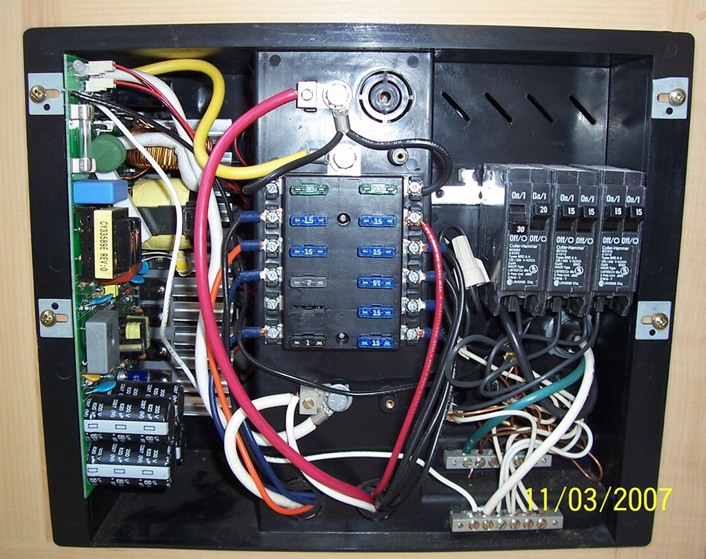
A close up of the AC neutral and the shore line earth ground buss bars.

The incoming shore line cord green ground wire, all 120 VAC romex cable grounds, and, there is a larger no 10 awg bare copper wire I am pointing to in the pic connects on that grounding buss bar. The no 10 awg bare copper wire is buried behind all the wires, but you can see part of it with the red arrow pointing to it.
Here is the outside of the camper showing where that large # 10 awg wire comes outside, attaches to the steel trailer frame, and jumps to the camper siding. This creates the hazard protection if a 120 VAC hot wire touches the siding or the frame. This connection to the frame has been known to corrode badly at times and there is nothing to tell you, this safety feature is lost until the shock hard presents itself. This pic has a green wire that I added. That is not Sunline supplied but the bare copper is.
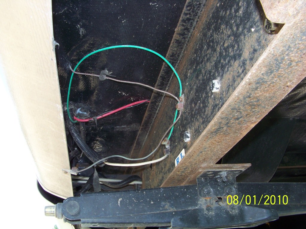
In that same pic, the large white wire is DC negative off the power converter DC negative and grounds right to the trailer frame.
When this connection is made like this, your PD converter case would be common to DC common and should show continuity "if" the earth ground connection wire is working back at the incoming shore line cord.
See what your camper has back at the old power converter area where the 120 VAC comes into the camper and all the romex grounds and the shore line cord ground wires reside. That area should have that frame grounding wire there and then also attach to the siding outside. It is the only tie between the shoreline earth ground and the steel on the camper. The wire may exist, but it may be corroded at the frame not making contact. If is grounding wire is totally missing, it should be added as there is no shock hazard protection then.
In an isolated DC negative system on a camper and how they are built using the steel frame as a wire, how is the AC shock hazard mitigated from coming in contact with the steel frame or siding?
Hope this helps
John
__________________
Current Sunlines: 2004 T310SR, 2004 T1950, 2004 T2475, 2007 T2499, 2004 T317SR
Prior Sunlines: 2004 T2499 - Fern Blue
2005 Ford F350 Lariat, 6.8L V10 W/ 4.10 rear axle, CC, Short Bed, SRW. Reese HP trunnion bar hitch W/ HP DC
Google Custom Search For Sunline Owners Club
|
|
|
|
|
05-18-2020, 09:46 PM
|
#52
|
|
Moderator
Join Date: Nov 2006
Location: Ohio
Posts: 12,656
SUN #89
|
Your truck and camper make a nice looking setup!  Thanks for sharing
__________________
Current Sunlines: 2004 T310SR, 2004 T1950, 2004 T2475, 2007 T2499, 2004 T317SR
Prior Sunlines: 2004 T2499 - Fern Blue
2005 Ford F350 Lariat, 6.8L V10 W/ 4.10 rear axle, CC, Short Bed, SRW. Reese HP trunnion bar hitch W/ HP DC
Google Custom Search For Sunline Owners Club
|
|
|
|
|
05-19-2020, 06:57 AM
|
#53
|
|
Senior Member
Join Date: Jan 2020
Location: Maryland
Posts: 143
SUN #11755
|
Maybe I wasn't clear in the previous post, but All wiring connections (both AC & DC) to the frame, and the AC grounding wire to the siding were dis assembled, cleaned to bare metal and reassembled with new bolts, nuts or self tapping screws into new holes. All of these were ohm checked against the ground pin on the cord. All showed 0.0Ω to 0.01Ω.
I'll go out and open the case, and recheck it.
__________________
|
|
|
|
|
05-19-2020, 08:18 AM
|
#54
|
|
Moderator
Join Date: Nov 2006
Location: Ohio
Posts: 12,656
SUN #89
|
Quote:
Originally Posted by Torskdoc423
Maybe I wasn't clear in the previous post, but All wiring connections (both AC & DC) to the frame, and the AC grounding wire to the siding were dis assembled, cleaned to bare metal and reassembled with new bolts, nuts or self tapping screws into new holes. All of these were ohm checked against the ground pin on the cord. All showed 0.0Ω to 0.01Ω.
I'll go out and open the case, and recheck it.
|
Hi Larry,
Sorry for not understanding your prior note. This one "seems" to be clear enough but something is not adding up.
Let me say this back to you, tell me if I misunderstood what you said. Or we may discover the mystery.
1. Per the blue text above, you verified that the shore line power cord earth ground pin had continuity to the camper frame and siding.
2. You stated the DC negative had continuity to the camper frame.
3. Are those 3 statements correct? If they are, then we have a mystery yet to be understood.
You just stated if I understood it right, that the shore line power cord earth ground pin has continuity to both the frame and DC negative. If that is the case, then why in this picture is the power converter metal case that has a bare copper ground wire to the metal outlet box not showing continuity to DC negative? I made an assumption that the metal outlet box is grounded.
Think about it, something is missing if those statements are correct. The DC negative should be reading continuity to the converter case by way of the DC negative frame ground and the AC earth ground at the frame.
There is only one point in the wiring that the shore line earth ground wire connects to the camper frame & siding which is the buss bar grounding wire at the old converter location when the shore line cord enters the camper. That may grounding wire area may be suspect something is amuck there.
Curious on what you come back with, or point out what I am missing.
Thanks
John
__________________
Current Sunlines: 2004 T310SR, 2004 T1950, 2004 T2475, 2007 T2499, 2004 T317SR
Prior Sunlines: 2004 T2499 - Fern Blue
2005 Ford F350 Lariat, 6.8L V10 W/ 4.10 rear axle, CC, Short Bed, SRW. Reese HP trunnion bar hitch W/ HP DC
Google Custom Search For Sunline Owners Club
|
|
|
|
|
05-19-2020, 04:44 PM
|
#55
|
|
Senior Member
Join Date: Jan 2020
Location: Maryland
Posts: 143
SUN #11755
|
John:
Questions
1. YES.
2. YES.
Outlet is Grounded.
Trailer in Totally unpowered state. Did some ohm testing of the case against the AC and DC Ground points. See Pics.
Breaker box opened up and all neutral and ground buss screws rechecked for tightness and verified all neutrals and grounds are clamped on WIRE.
Why this one is UPSIDE DOWN I have no idea. Anyway. Unplug the cord from the outlet and remove the ground bonding wire. Meter leads on the DC NEGATIVE Lug, and the AC Ground tap in the outlet. 0.2Ω. Shows continuity between DC NEGATIVE and AC GROUND thru Chassis.

Again, the cord is unplugged, bonding wire disconnected from case.
Meter Leads at case ground lug, and outlet ground lug. OPEN. If there were a connection to DC NEG thru the case I should have gotten a reading. Same as meter leads on Negative DC Lug and Case (cord plugged in or unplugged).

This one the CORD is PLUGGED IN, no bonding wire. METER LEADS to Case ground lug and DC NEGATIVE TERMINAL. Basically the same circuit as Picture 1.

When I checked the case vs negative DC, the cord was UNPLUGGED. With the cord plugged in I get 0.2 to 0.3Ω. I presume this is NOT thru the case, but thru the Chassis.
Main Panel.
Romex from AC outlet comes out on left strain relief. Neutral to 1st
lug on front buss(neutral). Bare Gnd to 3rd lug on Back Buss (GND). I measured 0.3ohms from the Converter DC NEG Lug to the GND BUSS. Going the the chassis to the bare lead and up to the buss.
The Battery / Converter POS is the large red lead at the top. Note that I tied it all into the upper lug which fuses each side with a 30A fuse 1st. The old set up had the converter lead direct to the next lug down on the center direct to the circuits.

__________________
|
|
|
|
|
05-19-2020, 09:40 PM
|
#56
|
|
Moderator
Join Date: Nov 2006
Location: Ohio
Posts: 12,656
SUN #89
|
Larry,
Your hunting has been good. Good job and thanks for the pics to go with them.
The case on the converter is not tied internally to the DC negative output line. PD isolates the DC negative on purpose and lets the user decide if they want the DC negative to be common with anything else. And your tests show this.
Since you did your tests with the camper unplugged from any shore power, your readings are good and understood.
The very first test you showed the pics on, this one
Quote:
|
Unplug the cord from the outlet and remove the ground bonding wire. Meter leads on the DC NEGATIVE Lug, and the AC Ground tap in the outlet. 0.2Ω. Shows continuity between DC NEGATIVE and AC GROUND thru Chassis.
|
tells us that the DC negative and the shore line earth ground connection at the main panel is intact and operating like it should. This will protect the camper steel from becoming hot with AC power and allowing the AC supply breaker to to the camper trip when a dead AC short happens.
This all fits like it should. Is there anything on your end that does not seem correct at this point?
Thanks
John
__________________
Current Sunlines: 2004 T310SR, 2004 T1950, 2004 T2475, 2007 T2499, 2004 T317SR
Prior Sunlines: 2004 T2499 - Fern Blue
2005 Ford F350 Lariat, 6.8L V10 W/ 4.10 rear axle, CC, Short Bed, SRW. Reese HP trunnion bar hitch W/ HP DC
Google Custom Search For Sunline Owners Club
|
|
|
|
|
05-20-2020, 04:40 AM
|
#57
|
|
Senior Member
Join Date: Jan 2020
Location: Maryland
Posts: 143
SUN #11755
|
No. It works good. The only time I noticed the fans come on is when it's either got everything powered up (DC side) and the batery is drained some, or when I manually switch it to boost mode via the pendant. Which if i understand it is, as it should be. I have solid state and tube amps and receivers that get hotter than this, and they run just on natural convection. So it's good.
Thanks John for the help and pointers. She's going to inspection later this week or early next week (when I can get her in) then we'll go on a short "sea trials" trip to a local state park in June. I'll let ya know how that went.
Thanks again
Larry
__________________
|
|
|
|
|
05-20-2020, 09:03 PM
|
#58
|
|
Moderator
Join Date: Nov 2006
Location: Ohio
Posts: 12,656
SUN #89
|
Good deal and glad to help as we can.
Have a good trip in June. We go out this weekend here in OH. Made the reservation back in November. The park campgrounds are allowed to open 5/21.
John
__________________
Current Sunlines: 2004 T310SR, 2004 T1950, 2004 T2475, 2007 T2499, 2004 T317SR
Prior Sunlines: 2004 T2499 - Fern Blue
2005 Ford F350 Lariat, 6.8L V10 W/ 4.10 rear axle, CC, Short Bed, SRW. Reese HP trunnion bar hitch W/ HP DC
Google Custom Search For Sunline Owners Club
|
|
|
|
|
05-28-2020, 02:53 PM
|
#59
|
|
Senior Member
Join Date: Jan 2020
Location: Maryland
Posts: 143
SUN #11755
|
Took her for the Md. State Inspection. PASSED! Mechanic (who also holds a Master Electrician license....go figure), loved the electrical installation. He suggested a non metallic cover over the converter, but I already had an answer for that. The Wall between the outer section and the converter. Nothing goes in the converter compt. except Air! 3/8" 2x4' panel cut down to size, and screw to existing framing for bed and cabinet. The brake shoes are down to 5/32 so I'll probably replace them over the winter.
Post availability shakedown cruise scheduled for June 14 thru 19 @ St. Janes Island State park in Crisfield. (about 140 miles away as the crow flies). Give the F-350 a workout, but so far it seems like it doesn't notice it has 2-1/2 tons hanging off the bumper. LOL! Golden age pass comes in Handy. 1/2 off camping for Seniors in Md Sun/Thu nights. Paid less for 4 nights than at most motels for 1 night! Nothing like stiffing the State..   and legal to boot!
Larry
__________________
|
|
|
|
|
05-29-2020, 10:03 AM
|
#60
|
|
Moderator
Join Date: Nov 2006
Location: Ohio
Posts: 12,656
SUN #89
|
Glad the inspection passed.
It sounds like the inspection was done right and not pencil whipped like some are. The trailer inspection done right, is a good thing as many trailer owners do not know to pay attention to certain aspects of the running gear and braking setup. And I know this is, always was a cost battle for the shop. Many times they can only charge fixed few for any trailer which may not be adequate in all cases to cover the shops costs. They should create a reasonably priced inspection that will look deeper, better and then create the state inspection as part of it.
Happy camping in June. We made it out last weekend and it was great to get out.
__________________
Current Sunlines: 2004 T310SR, 2004 T1950, 2004 T2475, 2007 T2499, 2004 T317SR
Prior Sunlines: 2004 T2499 - Fern Blue
2005 Ford F350 Lariat, 6.8L V10 W/ 4.10 rear axle, CC, Short Bed, SRW. Reese HP trunnion bar hitch W/ HP DC
Google Custom Search For Sunline Owners Club
|
|
|
|
|
|
|
Currently Active Users Viewing This Thread: 1 (0 members and 1 guests)
|
|
|
 Posting Rules
|
You may not post new threads
You may not post replies
You may not post attachments
You may not edit your posts
HTML code is Off
|
|
|
|
 » Recent Sunline Discussions
 |
|
|
|
|
|
|
|
|
|
|
|
|
|
|
|
|
|
|
|
|
|
|
|
|
|
|
|


 Linear Mode

