 |
|
 09-27-2023, 12:50 PM
|
#1
|
|
Member
Join Date: Oct 2015
Location: New York
Posts: 67
SUN #7928
|
New Issue with Hydroflame Furnace 8531-III
I was proceeding to start up the furnace at the rv my brother stays at which I own. It is a Sunline Solaris Model T-2970 made in 1995. Last year the furnace ran fine all winter. This year I had to replace the motor as it turned very hard. I also tested the DSI board which tested fine. Lastly, I purchased a new Dinosaur Electronics TDR relay. The furnace clicks on when prompted by the thermostat calling for heat and the blower kicks on with a good sail switch and the ignition lights for ten seconds in a series of 3 times and then the furnace kicks off. I need to see if I could get any input or help in where to look next. I've tested the connections and the continuity for the wires where I can access both endpoints and the wires tested good. I'm not sure what to do or where to look next. I have already blown out the exhaust chimney with the end piece to the outside both assembled and disassembled to make sure there are no obstructions. I'm open to all suggestions or ideas that will get this furnace operational before the cold sets in. So far, all the suggestions that I have received through this forum have been tried and were successful in getting the furnace going every time I ran into an issue. Thank you
__________________
__________________
|

|

|
|
09-28-2023, 06:54 PM
|
#2
|
|
Moderator
Join Date: Nov 2006
Location: Ohio
Posts: 12,656
SUN #89
|
Hi Randy,
Sounds like you have done some good digging into this. I'm going to split apart your description a little to help clarify a few things.
Quote:
Originally Posted by RandyJ55

I was proceeding to start up the furnace at the rv my brother stays at which I own. It is a Sunline Solaris Model T-2970 made in 1995.
Last year the furnace ran fine all winter. This year I had to replace the motor as it turned very hard.
I also tested the DSI board which tested fine. Lastly, I purchased a new Dinosaur Electronics TDR relay.
The furnace clicks on when prompted by the thermostat calling for heat and the blower kicks on with a good sail switch and the ignition lights for ten seconds in a series of 3 times and then the furnace kicks off.
I need to see if I could get any input or help in where to look next.
I've tested the connections and the continuity for the wires where I can access both endpoints and the wires tested good.
I'm not sure what to do or where to look next. I have already blown out the exhaust chimney with the end piece to the outside both assembled and disassembled to make sure there are no obstructions.
I'm open to all suggestions or ideas that will get this furnace operational before the cold sets in. So far, all the suggestions that I have received through this forum have been tried and were successful in getting the furnace going every time I ran into an issue. Thank you
|
Need to clarify your wording on the text in blue.
Quote:
|
tthe ignition lights for ten seconds in a series of 3 times, then the furnace kicks off.
|
You used the words, "the ignition lights", which of the 3 situations below fit?
1. Do you mean the ignition sparks for 10 seconds, just no gas burner running?
2. The gas burner actually did light and burned for 10 seconds, then the gas valve and ignition shut off, it waited, then relights the gas burner and ignition for 10 seconds and shut down, then tried a 3rd time, and the burner started but yet a 3rd time again shut down, and it goes out on safety and shuts down.
3. It is doing something else other than what I stated above; if so what?
Also, which part number Dinosaur board and Dinosaur timing relay are you now using?
Hope this helps
John
__________________
Current Sunlines: 2004 T310SR, 2004 T1950, 2004 T2475, 2007 T2499, 2004 T317SR
Prior Sunlines: 2004 T2499 - Fern Blue
2005 Ford F350 Lariat, 6.8L V10 W/ 4.10 rear axle, CC, Short Bed, SRW. Reese HP trunnion bar hitch W/ HP DC
 Google Custom Search For Sunline Owners Club
|
|
|
|
|
09-29-2023, 07:37 AM
|
#3
|
|
Member
Join Date: Oct 2015
Location: New York
Posts: 67
SUN #7928
|
Thank you for responding to my post regarding my Hydro flame 8531 -III gas furnace. In response to your question my furnace does light and blow out heat for 10 seconds a series of 3 times in and then shuts off. The furnace actually blows heat out of the external chimney. I will have to investigate what board and TDR I am using but I used them for the entire winter last year. There are a couple of variables that I should mention, and that being that a few of the wires like the thermostat wire and a red wire have been spliced and now have a plastic-coated male and female plug rather than a solid wire. Another thing I noticed is that the on and off switch on the outside does function but has no bearing on affecting the system turning on when the thermostat is prompted for heat. I recently changed the motor as the other one barely would turn . I got the correct applicatio0n as both the metal and the plastic wheel have to be centered in their respective cavities without restriction. I'm rather bothered by the fact that each thermostat on, blower on, then after a delay, the ignition to heat cycle last 10 seconds. I have never accessed the flame sensor or the limit switch before and I did blow the chimney out and into the exhaust cavity with a wand on my air compressor. I do realize that any obstruction would shut down the heat cycle. The motor I purchased was a 37357 PF26157Q 8531-35 III, the board was an Atwood 31501 for Hydroflame furnace, and the TDR was 12VDC ASIN: B01M9K2U78, 4 second delay, 2-minute cool down cycle. I hope I was able to provide you the information you asked for. Im pretty much wide open for suggestions or running certain tests, if required. I do have a voltmeter and will check whatever you recommend at this point.
Thank you
__________________
|
|
|
|
|
09-29-2023, 08:43 PM
|
#4
|
|
Moderator
Join Date: Nov 2006
Location: Ohio
Posts: 12,656
SUN #89
|
Hi Randy, OK here are some thoughts to line up with your added info.
I'll insert in blue some quick answers and then elaborate more
Quote:
Originally Posted by RandyJ55
Thank you for responding to my post regarding my Hydro flame 8531 -III gas furnace. In response to your question my furnace does light and blow out heat for 10 seconds a series of 3 times in and then shuts off. The furnace actually blows heat out of the external chimney. I will have to investigate what board and TDR I am using but I used them for the entire winter last year.
OK understand, glad we have this verified.
There are a couple of variables that I should mention, and that being that a few of the wires like the thermostat wire and a red wire have been spliced and now have a plastic-coated male and female plug rather than a solid wire.
The thermostat wire being joined with one of these plugs is not a concern. But you said a red wire. Depending on what exact red wire is spliced, it may or may not be a concern. Atwood used red for a few things. The one that is concerning is the high voltage ignition red wire. OR a flame sensor feedback red wire. If they are fan motors or board power wires that is not such a concern. Will explain more on this in a bit.
Another thing I noticed is that the on and off switch on the outside does function but has no bearing on affecting the system turning on when the thermostat is prompted for heat.
The 85 series -III had two vintages of wiring and how the toggle switch worked. The toggle switch shut down the gas valve operation on the earlier vintage, but the fan could run. And that early vintage may also have the remote flame sense probe. More on this flame sense in a moment. On the later vintage of the -III, the toggle switch cut all power to the furnace.
I recently changed the motor as the other one barely would turn . I got the correct applicatio0n as both the metal and the plastic wheel have to be centered in their respective cavities without restriction.
OK understand, that was a good thing to replace the motor
I'm rather bothered by the fact that each thermostat on, blower on, then after a delay, the ignition to heat cycle last 10 seconds.
I am going to talk about your in red highlight wording below.
I have never accessed the flame sensor or the limit switch before and I did blow the chimney out and into the exhaust cavity with a wand on my air compressor. I do realize that any obstruction would shut down the heat cycle.
The motor I purchased was a 37357 PF26157Q 8531-35 III, the board was an Atwood 31501 for Hydroflame furnace, and the TDR was 12VDC ASIN: B01M9K2U78, 4 second delay, 2-minute cool down cycle. I hope I was able to provide you the information you asked for. Im pretty much wide open for suggestions or running certain tests, if required. I do have a voltmeter and will check whatever you recommend at this point.
Thank you
|
What you are describing points to the fact that the controls are not seeing the flame sense circuit feedback or the flame sense on the board has issues. When the trial for ignition sequence is activated, the blower has run long enough to purge out any leftover gas fumes. Then the PC board opens the gas valve and sends high voltage to the igniter to create the spark to light the gas.
What happens next is where the problem is pointing to. There is a flame sense circuit that has to receive a signal that the flame is burning. If there is no flame sense burning signal coming back to the PC board, then the system thinks the flame never started or blew out. It only allows so many seconds of the gas valve with no flame sense coming back so it does not pump raw gas into the system for a long time. If the flame sense does not come back as a good signal in time, it shuts down the gas valve, shuts down the ignition, and starts timing to let the blower run and purge the chamber. Then it starts the ignition sequences all over. It only does this for 3 tries to light and get a flame sense coming back, after 3 times trying, it shuts down on safety and will not try again until you reset it.
Now to the flame sense system, Atwood had two styles within the -III rev furnace. We have to figure out which one you have.
Remote Sense: a separate probe inserted into the combustion chamber next to the ignition probes that, when it gets hot, sends a millivolt signal back to the PC board to say the flame is on.
Local Sense: This is the newer kind, the next generation of flame sense; it uses the actual igniter probe as the sensor when the igniter probe heats up from the flame, it sends back a millivolt signal to the PC board. This only uses one bid red wire on the igniter probe from the outside.
You will have to tell us which system yours is, the remote or local?
This pic is from an 85 series III with local sense, only one big red wire.

Look at yours. Are there two wires going in by the igniter wire into the combustion chamber or only 1? Do not get mixed up with the red gas valve wires.
The local sense would look like this. This is off an 85 series -IV with local sense, but it is all I have to show the signal igniter wire connection.
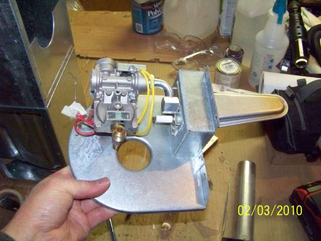

If you look at the white porcelain, that is the igniter probe, and there is a spade plug-in terminal on the outside for the high voltage thick red wire to plug into it not shown.
If your has two wires going inside the gas burner, the igniter and the remote flame sense probe, then you have the remote system. If there is only one wire, then it is the local sense.
Have a look and see.
Also, what we are hunting for is why you are not getting feedback to the PC board for flame sense.
It might be these things:
-Bad PC board; we will call this low odds right now since it worked last year, and you replaced it.
- You are not getting the flame sense millivolt signal back to the PC board.
A. If you have the single local flame sense, the spade terminal gets rusty over time, and while the high voltage will pass to light the flame, the millivolt feedback can get lost in the rust. Try cleaning the connection.
B. If you have the remote flame sense two-wire setup, the same thing: check the terminal for rust and clean it up.
C. You have an issue inside the gas burner; the screen that spreads the flame gets rusted and rotted out sometimes. If the flame does not spread right, the heat may not warm the probe correctly. To check this, you must take the gas burner out and look at what is inside. You should not have to remove the furnace from the camper, but you do have to remove the exhaust pipe and unhook the gas pipe. The burner and gas valve will come out as one unit.
D If there are any splices in the flame sense wires or igniter wires, this could affect the flame sense feedback.
This older 2003 service manual may help https://www.sunlineclub.com/forums/d...o=file&id=5631
The 85 series is what you are looking for, and the 85-III has the two versions of the wiring diagram on PDF pages 10 & 11 for local sense and remote sense.
Sort through all this and report back.
Take pics when you get into this. We can help better if we can see what you have.
Hope this helps
John
PS, We do have two retired RV techs here in the club. If they see your post, they may chime in too. I myself have never seen the older remote flame sense probe inside the gas burner. All the ones I have worked on, have been local sense.
__________________
Current Sunlines: 2004 T310SR, 2004 T1950, 2004 T2475, 2007 T2499, 2004 T317SR
Prior Sunlines: 2004 T2499 - Fern Blue
2005 Ford F350 Lariat, 6.8L V10 W/ 4.10 rear axle, CC, Short Bed, SRW. Reese HP trunnion bar hitch W/ HP DC
Google Custom Search For Sunline Owners Club
|
|
|
|
|
10-02-2023, 05:14 AM
|
#5
|
|
Member
Join Date: Oct 2015
Location: New York
Posts: 67
SUN #7928
|
Thank you again for providing me with this essential information. I didn't realize that the gas burning unit could be separately removed. From what I see, there is just one red wire that goes into the gas burner assembly. there is also two yellow wires and the thick high voltage wire for the ignition. I believe that I should remove the gas burner unit to get a closer look after insuring that the flame sense and igniter wires are not spliced. The weather is supposed to be nice this week up here in NY so I plan to put a plug or a cap on the end of the furnace gas line so my brother can use his stove in the event that I do have to replace parts on the burner or gas valve assembly. I will also look at the service manual you linked to before proceeding . I will let you know what I find. Thanks again.
__________________
|
|
|
|
|
10-02-2023, 07:05 AM
|
#6
|
|
Moderator
Join Date: Nov 2006
Location: Ohio
Posts: 12,656
SUN #89
|
OK, good hunting. I look forward to your report back.
This should be the flare plug you will need for the gas line, assuming yours uses 3/8" soft flex copper like most all Sunlines.

__________________
Current Sunlines: 2004 T310SR, 2004 T1950, 2004 T2475, 2007 T2499, 2004 T317SR
Prior Sunlines: 2004 T2499 - Fern Blue
2005 Ford F350 Lariat, 6.8L V10 W/ 4.10 rear axle, CC, Short Bed, SRW. Reese HP trunnion bar hitch W/ HP DC
Google Custom Search For Sunline Owners Club
|
|
|
|
|
10-09-2023, 06:50 AM
|
#7
|
|
Member
Join Date: Oct 2015
Location: New York
Posts: 67
SUN #7928
|
Hi John, Thanks for your input. I found that the old burner head was broken and the dual sense electrode and surrounding metal was blacked by burner head issues. I also noticed that the dual sense electrodes were over 3/8 away from the burner head and the prongs spread more that 1/8 apart. I need to know which part of the electrode the orange and black wire attach to because I ordered and received a new burner head and cleaned up the electrodes and reset the spacing while at the same time i ordered a new #37517 dual sense electrode which will be here in 2 days. I want to do a test run with the gas off and capped to see if the old electrode at least sparks when it is supposed to after the fan and time delay sequence clicks to green light the ignition. I believe that the orange wire goes on the bigger part of the electrode but I'm not sure. I appreciate any feedback for clarification. Thank you.
__________________
|
|
|
|
|
10-09-2023, 12:30 PM
|
#8
|
|
Moderator
Join Date: Nov 2006
Location: Ohio
Posts: 12,656
SUN #89
|
Quote:
Originally Posted by RandyJ55
snip...
I also noticed that the dual sense electrodes were over 3/8 away from the burner head and the prongs spread more that 1/8 apart.
I need to know which part of the electrode the orange and black wire attach to because I ordered and received a new burner head and cleaned up the electrodes and reset the spacing while at the same time i ordered a new #37517 dual sense electrode which will be here in 2 days.
I want to do a test run with the gas off and capped to see if the old electrode at least sparks when it is supposed to after the fan and time delay sequence clicks to green light the ignition. I believe that the orange wire goes on the bigger part of the electrode but I'm not sure. I appreciate any feedback for clarification. Thank you.
|
Hi,
This is where taking pics helps, and posting them so we can see what you are seeing.
What I think you are asking for is which wire goes on the ignition electrode and which wire goes on the remote flame sense probe at the gas burner.
If that is the question, here is what I can offer.
Atwood "normally" uses a big red wire with a heavy insulation cover on it for the ignition electrode. You are stating you have an orange wire; well over time, the red may have faded into an orangeish color. But here is a way to backtrack to what is the ignition wire.
Due to the high voltage of the ignition, the wire insulation has to handle that high voltage, so it is thicker. Also, the PC board has a coil on it to create that high voltage; you will start at the PC board and look for the round black coil on the PC board.
It would look like what is in this pic; see the round black coil with the red/orange wire on it. NOTE: This PC board may differ slightly from yours, but the high-voltage coil should look the same.

If your orangish color wire, with a heavy larger insulation case on it, starts at the round black coil, then you know that wire is the ignition.
The ignition wire needs to plug into the ignition electrode at the burner. Now to sort out which connection is the ignition electrode at the burner head. See page 25 in the manual I linked you to in my last response above. There is a picture of the one wire, "local sense" and the 2 wire "remote sense" setup. It looks like this;

You want the remote sense setup with 3 probes since your older furnace is set up with the remote sense system.
The ignition electrode (which has a porcelain insulator on it) is 1/8" away from the ground pin. The ground pin probe is bare and spot-welded to the metal housing with no porcelain insulator. Those 2 probes are straight, with no bend at the end of them. Put the ignition wire, which we think is your orange/red one, on the ignition electrode. But confirm that the orangeish wire starts at the round black coil on the PC board.
Next is your black wire. The wiring diagram on page 11 of the manual for the 85-III remote sense setup shows the remote sense flame probe is a black wire, and it will connect to the PC board in the push-on wire connector, not the high-voltage coil. At the gas burner, the remote sense probe is the probe that has a bend in the end of it, has a porcelain insulator on it, and is 1/4" away ignition electrode and ground pin. The black wire goes on the bent end flame sense probe. Check that this wording fits what you have in front of you.
If this does not sort this out, please post pics of the new burner showing the 3 probes and the PC control board, and we can back into it from your pics.
Hope this helps, and good luck,
John
__________________
Current Sunlines: 2004 T310SR, 2004 T1950, 2004 T2475, 2007 T2499, 2004 T317SR
Prior Sunlines: 2004 T2499 - Fern Blue
2005 Ford F350 Lariat, 6.8L V10 W/ 4.10 rear axle, CC, Short Bed, SRW. Reese HP trunnion bar hitch W/ HP DC
Google Custom Search For Sunline Owners Club
|
|
|
|
|
10-09-2023, 12:32 PM
|
#9
|
|
Moderator
Join Date: Nov 2006
Location: Ohio
Posts: 12,656
SUN #89
|
If you need help posting pic, see here.
There are 3 ways to add pics.
1. Upload pics to a specific post, attaching them at the end of the post.
2. Linking them in from a public viewable web photo hosting service you have.
See here for 1 and 2 https://www.sunlineclub.com/forums/f...html#post86041
3. You can upload pics to the forum in your own personal photo album. Then, link them to anywhere in the text of a post. See here for how to create an album. https://www.sunlineclub.com/forums/f...html#post87945
If you still get stuck, let us know.
__________________
Current Sunlines: 2004 T310SR, 2004 T1950, 2004 T2475, 2007 T2499, 2004 T317SR
Prior Sunlines: 2004 T2499 - Fern Blue
2005 Ford F350 Lariat, 6.8L V10 W/ 4.10 rear axle, CC, Short Bed, SRW. Reese HP trunnion bar hitch W/ HP DC
Google Custom Search For Sunline Owners Club
|
|
|
|
|
10-10-2023, 05:59 AM
|
#10
|
|
Member
Join Date: Oct 2015
Location: New York
Posts: 67
SUN #7928
|
Hi John; Thanks for your feedback. I believe that my furnace does have the remote sense electrode since there are 2 wires and 2 straight prongs and one bent. I believe you stated that the black wire attaches to the bent one. I do have the replacement coming here within the next few days and when it does, I will install the remote sense electrode and the wires as you have indicated and hopefully the furnace will function as designed. I will keep you posted. Again, thanks for your insight
__________________
|
|
|
|
|
10-10-2023, 08:58 PM
|
#11
|
|
Moderator
Join Date: Nov 2006
Location: Ohio
Posts: 12,656
SUN #89
|
Hi Randy,
You are welcome. Good luck with your furnace. We are here to help as needed.
John
__________________
Current Sunlines: 2004 T310SR, 2004 T1950, 2004 T2475, 2007 T2499, 2004 T317SR
Prior Sunlines: 2004 T2499 - Fern Blue
2005 Ford F350 Lariat, 6.8L V10 W/ 4.10 rear axle, CC, Short Bed, SRW. Reese HP trunnion bar hitch W/ HP DC
Google Custom Search For Sunline Owners Club
|
|
|
|
|
10-15-2023, 12:20 PM
|
#12
|
|
Member
Join Date: Oct 2015
Location: New York
Posts: 67
SUN #7928
|
Hi John: The soldered end of the 36999 which has 2 straight prongs and one bent prong with a higher degree of porcelain., broke off. So, I reverted back to the 37517 which has 3 bent prongs using the same application that you recommended as I had to try something to get heat. The black wire is on the bent prong with the higher degree of porcelain as I determined that that is the flame probe. The ignition probe has the orange high intensity wire. After reassembling the burner valve assembly and the chimney, I tried the furnace and the fan runs then there is a click, and the furnace ignites, and the blower immediately shuts down. The ignition doesn't even make it to ten seconds and instead of the fan running, then a click, ignition and the continuation of the heat then cool cycle, I'm left with a furnace that won't run beyond 20-25 seconds. I've replaced the motor, the TDR, the burner head, and now am running with the incorrect electrode that, in theory, should still work. Fortunately, the 36999 is being replaced free from the vendor because the soldered end broke off one of the electrodes. It looks like I will have to go back to the drawing board to see why the blower shuts down when the ignition lights, and why the ignition shuts down afterwards. and then the blower tries to come on again. I may have to start from scratch again if it means a PC board, TDR, a complete harness with plug for the 8531-III and then the extraction and inserting the 36999-electrode in. I welcome any input or advice you may give me so I can get this furnace going correctly. It's very much appreciated. Thanks again for your time and expertise..
__________________
|
|
|
|
|
10-15-2023, 12:41 PM
|
#13
|
|
Member
Join Date: Oct 2015
Location: New York
Posts: 67
SUN #7928
|
Additional Information on 8531-III
John, I wanted to add that when my brother was turning up the thermostat to trip the furnace into operation that he claimed that one of the terminals got very hot when he turn up the temperature setting. I checked out the continuity on the thermostat afterwards and it seems to work fine but without being connected to the red and white wires.
__________________
|
|
|
|
|
10-15-2023, 01:56 PM
|
#14
|
|
Member
Join Date: Oct 2015
Location: New York
Posts: 67
SUN #7928
|
John, As I examine this Dometic heat only thermostat, I noticed that there is a burnt section between the white wire terminal and the anticipator slide. So at this point, I have to replace the thermostat but I'm curious about the root of the issue, cause and effect. I do also realize that I will need the 36999 electrode according to the 2003 manual link you sent me. That electrode should be here by Wednesday. I have to re examine and reset to get this right. Let me know what my burnt thermostat may indicate.
__________________
|
|
|
|
|
10-15-2023, 10:16 PM
|
#15
|
|
Moderator
Join Date: Nov 2006
Location: Ohio
Posts: 12,656
SUN #89
|
Quote:
Originally Posted by RandyJ55
After reassembling the burner valve assembly and the chimney, I tried the furnace and the fan runs then there is a click, and the furnace ignites, and the blower immediately shuts down.
The ignition doesn't even make it to ten seconds and instead of the fan running, then a click, ignition and the continuation of the heat then cool cycle, I'm left with a furnace that won't run beyond 20-25 seconds.
I've replaced the motor, the TDR, the burner head, and now am running with the incorrect electrode that, in theory, should still work. Fortunately, the 36999 is being replaced free from the vendor because the soldered end broke off one of the electrodes. I
t looks like I will have to go back to the drawing board to see why the blower shuts down when the ignition lights, and why the ignition shuts down afterwards. and then the blower tries to come on again.
I may have to start from scratch again if it means a PC board, TDR, a complete harness with plug for the 8531-III and then the extraction and inserting the 36999-electrode in. I welcome any input or advice you may give me so I can get this furnace going correctly. It's very much appreciated. Thanks again for your time and expertise..
|
Hi Randy,
The fan shutting down when the ignition fires off is a big problem and can cause many other issues. A sail switch inside the blower housing closes when the wind from the blower running fast enough blows it closed. When that sail switch opens due to the motor slowing down, it pulls the power from the PC board and shuts down the ignition sequence, which then the gas valve also goes down.
When the fan motor stops, that event will stop the ignition and shut off the gas valve. The fan motor is the next thing to sort out why it shuts down when the ignition starts.
Normally, the TDR keeps the motor running for a cool-down cycle once the T stat is satisfied and removes the call for heat.
Since the motor stopped as soon as the ignition started, this points to the lack of power in the furnace area. There appears to be enough power to run just the motor and, for a brief moment, enough power to start the ignition and power up the gas valve. But, when the motor, ignition, and gas valve are energized, the motor stops. The motor is only turned on and off the TDR, OR lacks enough 12 VDC power to power the system.
You need to determine why the motor is not running when the ignition sequence starts. Here are some of the possible causes.
1. You have a corroded ground terminal at the furnace when connected to the Sunline 12 VDC negative wire. If this connection is bad, it can pass some power but not enough power.
2. Something upstream of the furnace on the 12 VDC + supply wire is using too much power. Since you did not say you blew the fuse from the power converter that feeds the furnace, that does not mean something else is using up the power, or you have a low voltage issue.
You can try this to see if the voltage drops. Using a volt meter, clip onto the + 12 VDC and - 12 VDC right where it connects to the furnace. That live power should be in the 12.6 VDC or higher voltage range before the furnace comes on if you are only on fully charged battery power. If the power converter works, the voltage should be 13.2 volts or higher. Make sure you have this voltage before starting the furnace. Ideally, get the meter probes on both of the 12 Volt - & + wires power going to the TDR.
Leave the meter on, turn the furnace on, and look at the voltage. Record the voltage when the motor is running and no ignition yet. Keep watching the voltage and wait for the trail for ignition. As soon as the gas burner comes on and the ignition, record that voltage and compare it to when the motor shuts down. Tell us all the voltage readings.
Also, make sure whatever else was on inside the camper, lights, radio, roof antenna, etc, is on when you had your last test when the motor stopped running. It may be there is too much 12-volt power being used at the same time due to other issues.
Regarding the T stat issue, to do the test above and continue the furnace testing without a T stat, you can unhook the 2 wires on the T stat and jump them together to run the furnace constantly by just touching the 2 wires together. To stop the furnace, unhook the 2 wires. It will then simulate the T stat going on and off. The blower etc, will still cycle down in time as it should.
As to why the T stat got hot, I'm not totally sure on this one. That T stat has a heat anticipator circuit that might get warm if the T stat wires have a low 12 DC voltage.
At this point, it is yet to be known if the electrodes or the flame sense system, etc, are working or not. When the blower goes down, they go down, too, due to the blower stopping.
Pictures: I need pictures to see what you have to help better. Atwood or Dometic may have changed how the 3 electrode probes look, and look nothing like what was shown in the 2003 service manual. If you are taking pictures, show the inside of the T stat with the cover off, the TDR area, and the outside PC board and furnace. I may see something that needs to be corrected or be able to draw on the pics to show you what to look for.
Hope this helps
John
__________________
Current Sunlines: 2004 T310SR, 2004 T1950, 2004 T2475, 2007 T2499, 2004 T317SR
Prior Sunlines: 2004 T2499 - Fern Blue
2005 Ford F350 Lariat, 6.8L V10 W/ 4.10 rear axle, CC, Short Bed, SRW. Reese HP trunnion bar hitch W/ HP DC
Google Custom Search For Sunline Owners Club
|
|
|
|
|
10-16-2023, 04:41 AM
|
#16
|
|
Member
Join Date: Oct 2015
Location: New York
Posts: 67
SUN #7928
|
John , Thanks for your feedback. I will do the voltmeter test to check the voltage coming to the furnace. I do want to add that I definitely have the wrong electrode installed. I need the 36999. That will be here Wednesday as will a new sail switch and heat only thermostat. I can use the two wires once I reassemble. I hope to be able to locate the source of the issue and if found,I will let you know. Thanks again for your help.
__________________
|
|
|
|
|
10-16-2023, 05:28 AM
|
#17
|
|
Member
Join Date: Oct 2015
Location: New York
Posts: 67
SUN #7928
|
Hi John, I just watched a YouTube video which is 50+ minutes long and the guy working on his friends furnace which is a hydroflame 8531-III and he pointed to the bent electrode as the igniter and the straight prong on the other side of the ground as the flame sensor. I just need to clarify which is which because I had thought that the bent prong electrode was the flame sensor. I'm unclear now that I watched that video titled RV service and repair, 8531-III by Ozark Ethics. Let me know your thoughts
__________________
|
|
|
|
|
10-17-2023, 11:04 PM
|
#18
|
|
Moderator
Join Date: Nov 2006
Location: Ohio
Posts: 12,656
SUN #89
|
Quote:
Originally Posted by RandyJ55
Hi John, I just watched a YouTube video which is 50+ minutes long and the guy working on his friends furnace which is a hydroflame 8531-III and he pointed to the bent electrode as the igniter and the straight prong on the other side of the ground as the flame sensor. I just need to clarify which is which because I had thought that the bent prong electrode was the flame sensor. I'm unclear now that I watched that video titled RV service and repair, 8531-III by Ozark Ethics. Let me know your thoughts
|
Hi Randy,
In these cases, pictures are priceless; here is the video you described. You will have to scroll back to the start with this link
https://youtu.be/xSliED1d48A?si=Vo9XvHrRoWS7hIxA
As I stated, I have not seen up close or worked on the 85 Series III furnace. All my work has been on several of the 85 series IV next-generation furnaces.
This service manual picture was not specific enough to tell which probe with the igniter. It can easily be understood either way, primarily since the IV rev furnace only uses straight probes for the ignition.
After reviewing the video and double-checking it, I do agree the bent probe is the ignitor on the Rev III. It still has a 1/8" spark gap to the ground pin. And there is another feature that makes the bent probe fit with the igniter.
In the video, at time mark 20:52, it shows the probes but does not yet declare which probe is the igniter and which is the flame sense.
At time mark 27:19, he is pointing to the igniter next to the gas pipe connection. The key point is the probe next to the gas pipe.
At time mark 28:51 he is plugging in the black flame sense wire, which is on the opposite side of the gas pipe. This confirms the igniter is probe next to the gas pipe, which is the bent pin.
At time mark 32:13 he is plugging the large red/orange wire, we now know is the igniter wire, onto the probe next to the gas pipe, the igniter probe. The Rev IV furnace does not have that large wire boot that goes over the porcelain insulator, but the rev III does.
For spark only, the spark could jump the gap on either probe, but the metal they make the probes out of or the location at the burner may not work well if the flame sense is not on the straight pin.
So, with that video review, yes I agree the bent pin probe is the igniter, and it looks like the porcelain might be larger to fit better with the wire insulation boot.
You also mentioned you bought a new sail switch coming. The video talked about the high-temperature limit switch; heads up, before you think about changing either of them (sail or high temp), let's talk about how you can test if they are not working with the furnace intact before you tear the furnace apart. You must take out the entire motor blower blades to get to those sensors. It is a lot of parts to come out, and potentially the entire furnace out of the camper. If they test right, then the problem may be elsewhere. (you can test for if the voltage drops out to the igniter board after the hi-temp switch.)
He did mention insufficient LP gas volume, which is on the list of possible issues not to keep the burner running, but before we get into that, the blower must run correctly. If the blower cuts out, nothing will work right. Once sorted out, you can return to other problems and tests.
That video proved these furnaces need screens over the outside air intake and exhaust. That mud dauber nest was massive.
Hope this helps
John
__________________
Current Sunlines: 2004 T310SR, 2004 T1950, 2004 T2475, 2007 T2499, 2004 T317SR
Prior Sunlines: 2004 T2499 - Fern Blue
2005 Ford F350 Lariat, 6.8L V10 W/ 4.10 rear axle, CC, Short Bed, SRW. Reese HP trunnion bar hitch W/ HP DC
Google Custom Search For Sunline Owners Club
|
|
|
|
|
10-19-2023, 03:36 PM
|
#19
|
|
Member
Join Date: Oct 2015
Location: New York
Posts: 67
SUN #7928
|
I'm reluctant to get to the limit switch but I did take the 2 white wires, one connects to the circuit board and the other to the sail switch, and I ran a continuity test and I do have continuity but I don't know what else to test for . I did get a new Dometic heat only thermostat, the correct electrode set and I have a new sail switch coming as well as a blower motor and a new plastic blower wheel attachment as the old one had a broken piece where it is retained on the left side of the furnace and the replacement motor I put in September ended up being the wrong one as it was 1/2 too long and the cover had to be shifted to the left to accommodate. Once the new motor and cage comes in next Tuesday, I can begin reassembly. I expect the sail switch in tomorrow or Saturday. It's pretty much bare bones now with everything out but the limit switch. Please let me know if I can perform any other test on the limit switch remotely, if possible. Thank you for updating me on the igniter wiring setup. You can understand why I had conflicts between the igniter and flame probe. Hopefully I can get it running by next weekend. The weather looks like it will be nice here in Cohocton NY by midweek. Thanks again for your insight and diligence in helping me get this furnace right. Potentially,the only things I didn't change was the valve assembly and the limit switch for this 8531-III furnace.
__________________
|
|
|
|
|
10-19-2023, 04:59 PM
|
#20
|
|
Member
Join Date: Oct 2015
Location: New York
Posts: 67
SUN #7928
|
John, I have one more question. I had to bend the tab for the igniter wire because when it arrives, both tabs for the wires to connect to are straight and will jam straight into the gas valve assembly as is and the wires not the high tension boot won't go on. I got the igniter electrode assembly mounted and the burner head screwed to the valve assembly, but is the ground prong in the middle supposed to contact the burner head or should I elongate the holes to adjust it till it clears or simply try to bend it clear of contact? I should have taken some pictures when I extracted the unit so I would have as many questions. Let me know your thoughts. Thanks John]
__________________
__________________
|
|
|
|
|
|
|
Currently Active Users Viewing This Thread: 1 (0 members and 1 guests)
|
|
|
 Posting Rules
|
You may not post new threads
You may not post replies
You may not post attachments
You may not edit your posts
HTML code is Off
|
|
|
|
 » Recent Sunline Discussions
 |
|
|
|
|
|
|
|
|
|
|
|
|
|
|
|
|
|
|
|
|
|
|
|
|
|
|
|
|
|


 Linear Mode

