Hi Folks,
This post is about rebuilding worn pinion gear bushings on the Lippert rack and pinion drive system. Sunline used a few different slide drives over the years, the Lippert system came into use during the early year 2000 models. I’m not 100% sure if it was 2001 or 2002. It could have been split even between the years. The Barker slide drive, also a rack and pinion drive but a different style was before the Lippert on the larger super slides. (couch and table slide).
I happened to have my slide drive system apart when I was working on my camper frame and I noticed the bronze bushings where worn. Since I had part of the system apart, I decided to rebuild the bushings and glad I did. I’ll do this mostly with pics to be more helpful then a wording which can be harder to understand sometimes.
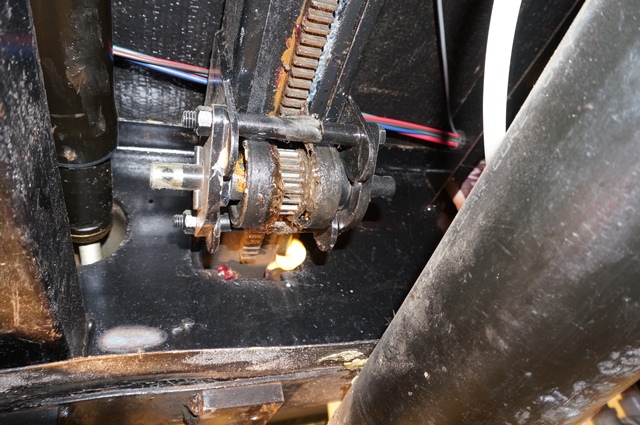
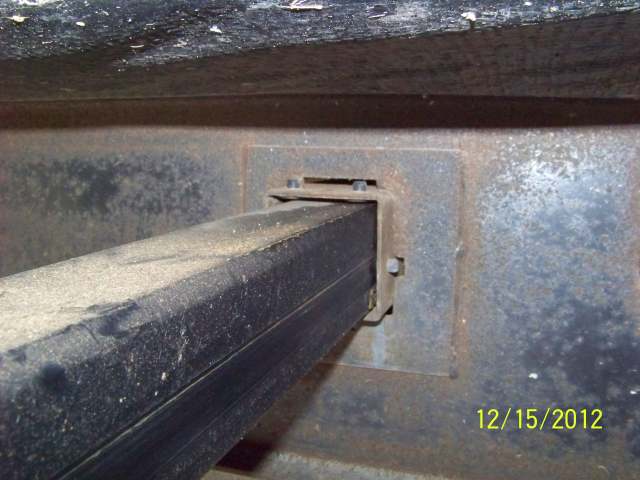
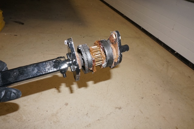
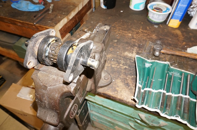
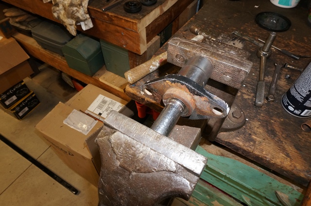
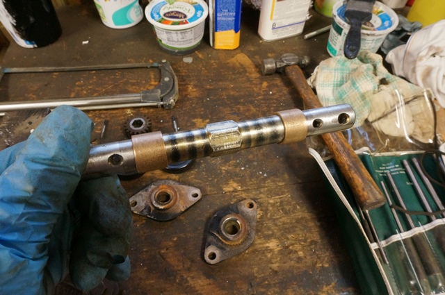
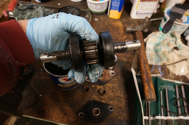
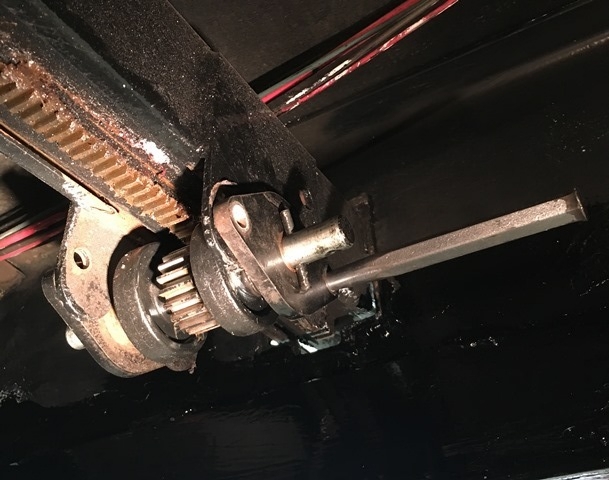
Here is slave driven slide arm pinion assembly with the square drive shaft still attached. The master rack pinion assembly looks the same just the square shaft is slightly smaller in square dimension.
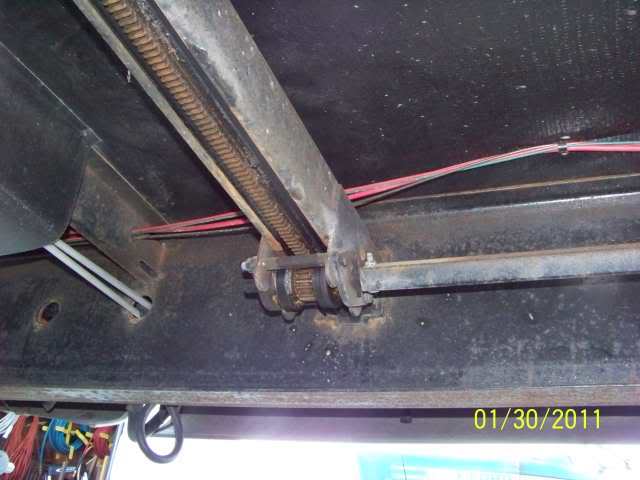
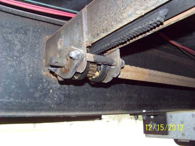
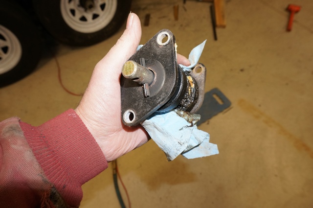
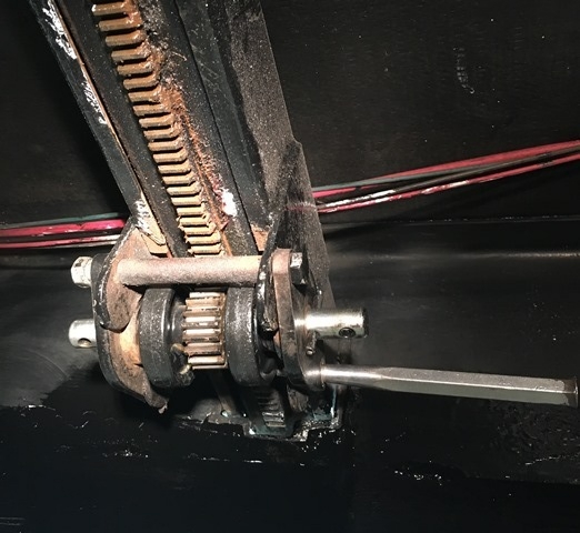
This is the master rack side view. On my camper the master rack slide arm is inside my tank compartment. And both pinion assembles are inside the camper frame. Not all campers are this way. I actually like the inside method as it keeps a lot of road dirt and grime out of the gear teeth and bearings.
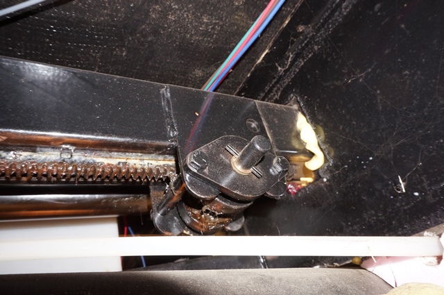
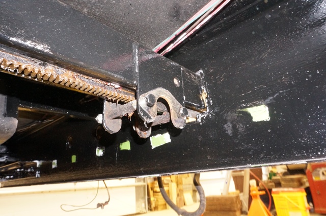
To start with you need to unhook the square shaft from the pinion shaft. I started with the master rack bolt and it came out fairly easy. It looks like this once the square shaft is off.
Next is to go to the slave rack pinion assembly and take the square shaft off that pinion assembly. Sometimes the 1/4” bolt is frozen up solid and or stuck in the pinion shaft. Since one end is unhooked, you can drop out the entire pinion assembly with the square shaft attached and deal with the frozen bolt out in the open.
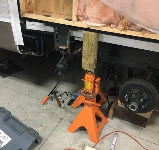
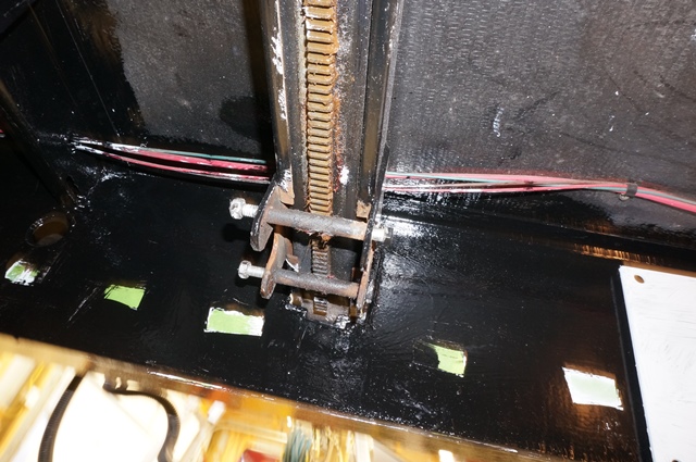
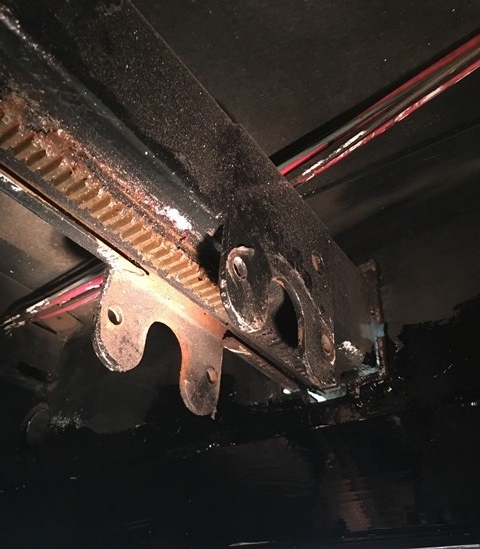
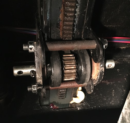
Before removing the pinion assembly, you need to lift the weight up off the slide arm you are working on. I used a bottle jack to just lift the arm approx. 1/16” to take the weight of. You can see when the weight is off as the top wear pads will be then touching on the slide arm housing. You can put the jack under the slide arm or the outside wall where the studs are. I had the slide apart so I used the wall. Do not jack in the center of the floor area, it may damage the floor.
I am referring to the 2 top nylon wear pads in this pic. In the pic there is clearance between the top of the arm and the pads. When you jack up the arm, stop when the clearance is all gone. Then the pinion assembly is unloaded from the slide weight.
Now you should be able to spin the arm rollers on the pinion shaft. If not, then the weight may not be off of it. Once the weight is off, take out the 2, 3/8” bolts
The entire pinion assembly will come out. I put the bolts back in the holes to keep track of them
And the entire assembly
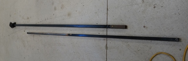
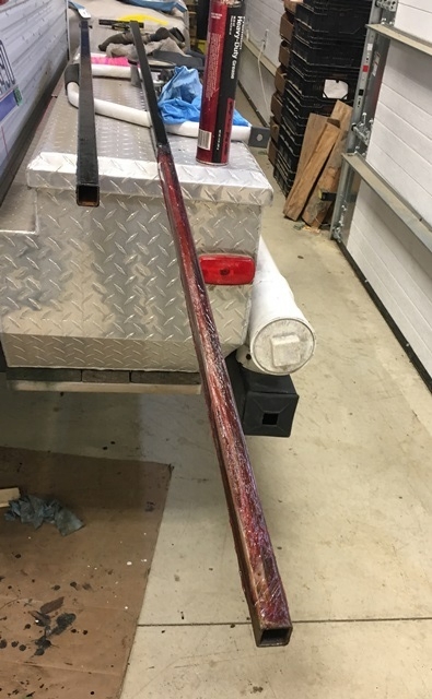
The square shaft is 2 pieces. An inner and an outer. They telescope together if they are not rusted solid.
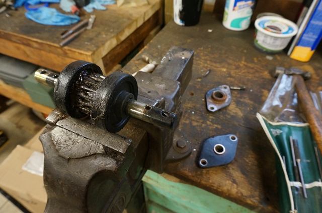
Here is the master rack pinion assembly. You can see the heavy wear in the bushing
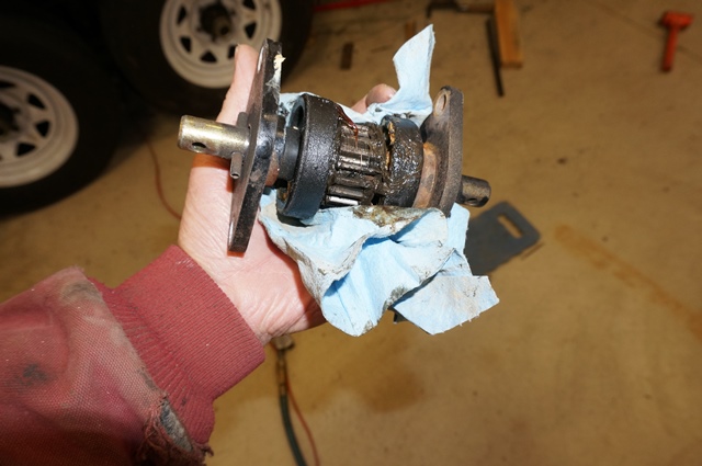
I noticed on my master rack inside bushing (the side with the square shaft on it,) wears the most. The outside master rack bushing not so much. And the slave drive rack inside bushing with the square shaft wears more than the slave rack outside bushing. But not as much as the master rack inside bushing. It seems the wear follows the torsion pressure exerted which the inside master rack bushing is taking the blunt of the load.
Now clean up all the parts and start taking each assembly apart.
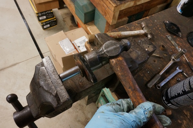
You drive out both roll pins on the ends
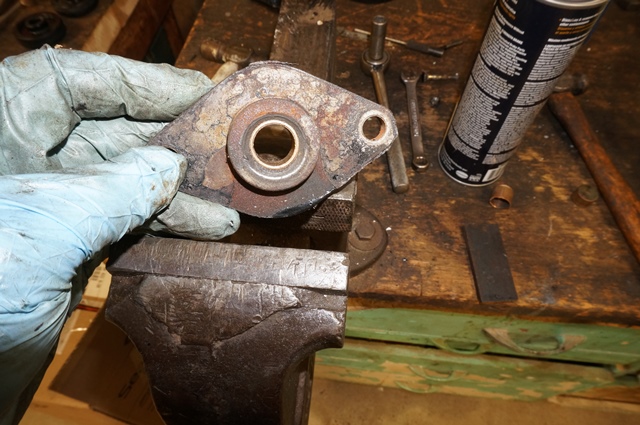
With the pins out, the end plates can now come off
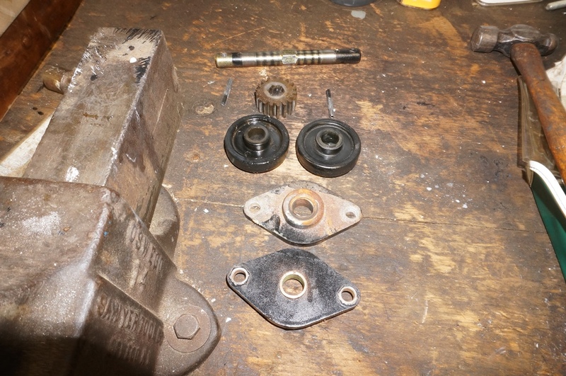
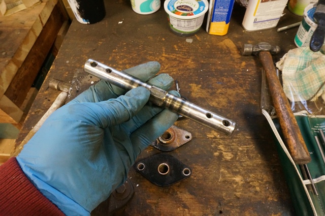
The plastic roller wheels then slide off and the gear which has a hex in the center, slides off or may need a gentle tap with a dead blow hammer. The parts look like this
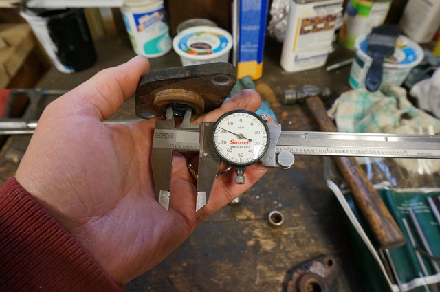
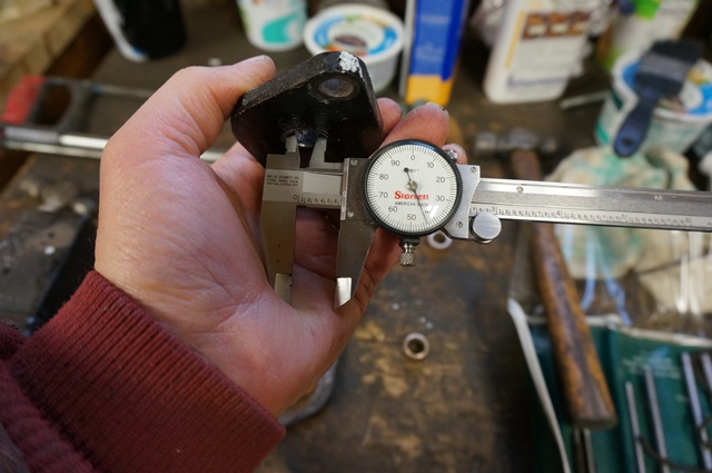
Here is the master rack inside bushing with 0.062” ID wear or 0.031” side wear. The bushing is only 0.062” thick cross section. It was half worn through.
This is the slave rack inside bushing. 0.043” ID wear or 0.225” side wear.
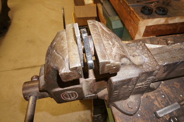
To press the bushing out, I use deep sockets in a vise. You need to find the right size sockets and remember metric too. They press right out.
If you feel heavy pressure on the vise clamp screw, a light tap on the housing and it will vibrate right on center and the bushing start moving. It did this on 2 of the 4 so I thought I would mention it.
In this case I went to the hardware store and bought new bronze bushings. $2.00 each. They were 1 1/8” long and I only needed 1/2" long. We have a small metal lathe so I cut them precisely in half. You also want to use fine emery cloth and polish the shaft where the bushing rides. Can't beat the price for $4 bucks you have all new bushings.
Test fit the bushings. My shaft had slight wear, about 0.003”. Since this shaft only wore 0.003 to 0.005” in 13 years of service, I reused the same shaft.
Then to press in the bushings. Again the back to the vise and some flat plates to not mar the ends of the bushing with the vise jaws. Line up the bushing and slowly press it in.
Once each end plate has a new bushing pressed in, check the shaft fit. It is common that a bushing will compress the ID a few thousands during the pressing operation. If it is too tight to spin free, ream the bushing slightly.
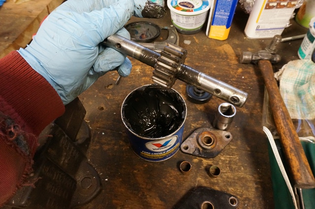
Now to assembling the unit. I myself use grease. It is a debate to use it or not. In my case, both pinions are inside the frame and do not get plastered with road grim. And the master rack is inside the tank compartment all covered up. Yes, I need to climb under and clean off the grease every so often and put new on, but the whole system runs smoother and the wear is acceptable to me. I have seen campers of other brands where the pinions are on the outside of the frame in the direct line of fire of road splash off the tires. They are beat and beat bad. The gear teeth are riding in dirt. In that case, greasing may be an issue with the road grime. When buying a camper, try to get one with the slide square shaft drive on the inside of the frame. I do not know if all Sunlines have them on the inside. I’m glad mine does.
The shaft and the pinion
The rollers. Mine had very little wear so I’m reusing them.
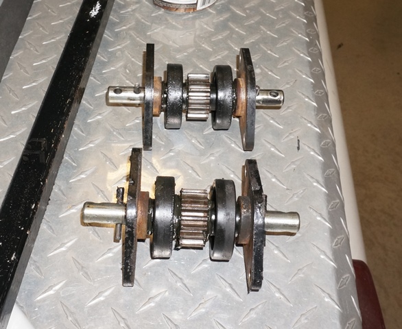
You put the end plates on and the roll pins in. Here are 2 rebuilt pinion assemblies.
After seeing this is a telescoping square shaft, I was shocked that after 13 years it was not rusted solid. I greased the inner shaft before inserting it to help prevent corrosion.
Now to put the assemblies back in. Heads up. You need to make sure the square shaft bolt aligns the same on both gear racks (slide arms). I chose to put the square shaft bolt straight up when I meshed the gears. This is so you are not out of time when you put the square shaft back on. Also, jack up the slide arm to take the weight off or you will not get the bolts to go in. There needs to be some running backlash on the gears.
It starts like this
I use a tapered punch to line up one hole and mesh the gears.
Then put in one bolt and spacer. Do not tighten yet.
Then pull the punch and put the second bolt and spacer in. The gears need to mesh right or the bolts will not go in. Wiggle the assembly as needed.
Now you do the other pinion assembly and when done, hook up the square shaft. Make sure you get the same tooth engaged so you do not have to rotate the shaft to line up the pinion shaft hole to not change the timing of the slide arms. A side note, the inner (smaller) side of the square shaft was on the master rack. The outer square shaft and had a plastic bushing inside it was on the slave rack pinion assembly.
Hope this helps someone in the future.
John


 Linear Mode


