 |
|
 02-26-2017, 06:39 PM
|
#61
|
|
Moderator
Join Date: Nov 2006
Location: Ohio
Posts: 12,654
SUN #89
|
Quote:
Originally Posted by Trailblazer

When I can get access to our 5th Wheel again later this year, I have something else to check now. A couple years ago I hit the worst asphalt heave in Michigan. It was so bad it almost felt the trailer could have gone airborne. Although at the time I couldn't see any structural damage, I never considered it could have caused some small damage that would get worse over time.
|
Hi Bill,
Thanks for the good words. Much appreciated.
For sure, check your frame. Especially look at the lower flange for "any" type of deflection, bend, twist or anything that is not true straight. Your 5'er floor plan and mine are very close to the same in regards to the rear living area camper. The overhung loads on the frame may be similar. From my rear spring hanger to the back of the frame where it attaches to the bumper is 102" as Sunline provided. (this is not my rear boxes included) And your slide is most likely hanging back like mine with a good amount on the cantilever beam area.
I seem to recall Gary saying one time, Kitty and his 5er had the factory couch in it that the weight an immense amount. Theirs was a full pull out bed I think. Does yours still have that couch? I know you changed out the swivel rockers when I last saw your rig.
Look over the whole frame but extra look right behind the rear axle hanger. That is the area that takes the blunt of the force and the lower flange wants to buckle after a towing road "event". If yours has any type of deformation, for sure soon is the time to reinforce this before it continues to ratchet itself weaker and bend down. Then your slide will be like mine....
Let us know what you find out when the time comes. Glad to help share the learning's...
John
__________________
__________________
Current Sunlines: 2004 T310SR, 2004 T1950, 2004 T2475, 2007 T2499, 2004 T317SR
Prior Sunlines: 2004 T2499 - Fern Blue
2005 Ford F350 Lariat, 6.8L V10 W/ 4.10 rear axle, CC, Short Bed, SRW. Reese HP trunnion bar hitch W/ HP DC
 Google Custom Search For Sunline Owners Club
|

|

|
|
02-26-2017, 08:29 PM
|
#62
|
|
Moderator
Join Date: Nov 2006
Location: Ohio
Posts: 12,654
SUN #89
|
Hi Steve,
You have very good questions, and ones that I have done a bunch of researching on trying to figure out how other brands and longer heavier campers are built. Here are some answers to them.
Quote:
Originally Posted by Mrtweety
John,
This is truly fascinating stuff. Amazing how sensitive the "square slide opening" is to seemingly minor beam deflections. I'm starting to wonder how they built these things correctly in the first place.
|
The slide opening in the camper and the slide room itself, actually has a fair amount of forgiveness for being out of square. That is, assuming the frame under the camper holds straight "enough". I did diagonal measurements on the slide and the opening. The slide room itself was square within 1/8" which I was surprised it was that good. The camper opening obviously was pretty far out of square in the condition it was in before I started on this.
There really is not a lot of bent beam in my case. Yes I have the problem but a small area behind the hanger bent and the angle is small. The 1 3/16" droop I measured is on a beam length of 95.5" and this comes out to be a whopping 0.713 degrees. Not much at all for the bend. It is the length that magnifies the issues. Bottom line, the frame cannot permanently deflect a lot or problems come which is what you have said. As long as the frame holds, there is plenty of operating clearance on the sides of the slide for things to wear and even accept a level of out of adjustment and still work.
How they build them to hold up to this? That is the learning here. From what I have tried to piece together, the RV industry jumped on the same frame type of steel used in Manufactured Housing. They call these thin I beams, MH beams. In the case of the manufactured house, that frame really only has to travel "once" normally from the factory to the home destination. The RV though has lots of miles and at much higher rates of speed over some really bad roads some times.
The frames we have are the "heavier" RV frames. They actually make them less rugged... The RV manufactures are up against, weight of the frame, verses function and cost. And then there are the many floor plans that have different loading patterns to them. I do not know how much failure analysis goes into every floor plan loading of the frame and does each manufacturer follow the same guidelines as everyone else?
I know that to make the heavier camper frames work, different RV manufactures use different techniques/tricks to make the thin I beams work. Northwood on your Fox, uses a weld shrink cambering technique on the top flange over the hanger area to help reduce the deflection of the beam. Palomino use to do this too on their Sabre campers. I do not know if they do it now still and what sizes, but in the 10" frame they have.
A new trick I found, I cannot recall the brand, they weld on a really heavy stiffener lat bar on the lower flange. That does 2 things. Helps the lower flange from buckling and also increases the area moment of inertia by a good amount since it is so far from the neutral axis. However I did not see any reinforcements from the flange to the web. The lower flange I'm sure is pretty flexible.
There are also some different thickness 10" I beam frames. Some have 1/4" flanges in place of 3/16", And some may be thinner too.
I'm sure there are other things done, those are the ones I have run into on I beam frames. The new thing is now on larger 5'ers is to go to a 12" frame. That too gives a good amount of area moment of inertia without a lot of weight. I just hope the reinforce the flanges from buckling when they do that.
I have a lead on one 2004 Sunline that is about as long as mine where I might get lucky and he has pictures of the top of the frame when he took the camper box off. I do not know if my frame or any other Sunline frames used the weld bead camber trick on the top flange over the hanger areas. I have not been able to find a quantitative amount of strengh gain from this process but it seems to work.
Quote:
Originally Posted by Mrtweety
Anyway - can you expound a bit on the lower flange welded bars you are now working with?
|
Sure. When I started this investigation I tried to back into what size forces occurred to caused the bend in the first place. After I figured out what the yield strength of the steel was, I had a place to start. The basic end result was, what I have is on the edge of being strong enough for the towing "events" the camper has incurred since Nov. 2003 when it was made. I needed to fix what was bent back to the original strength and I needed to make it stronger to not happen again.
The fix of the original was limited by the camper sitting on top of the frame. The frame fix itself would of been easier if the camper was not on top. No small task lifting the camper up off the frame though. So I had to create a way to fix the frame with camper in place and make the beam stronger then original. I'll answer some more in the questions below as they intermix here.
Quote:
Originally Posted by Mrtweety
Could this have been accomplished with adding a lower flange on the sister plates?
|
Well, I started this way by having a flange on the bottom of the sister plates.
See here, option 1
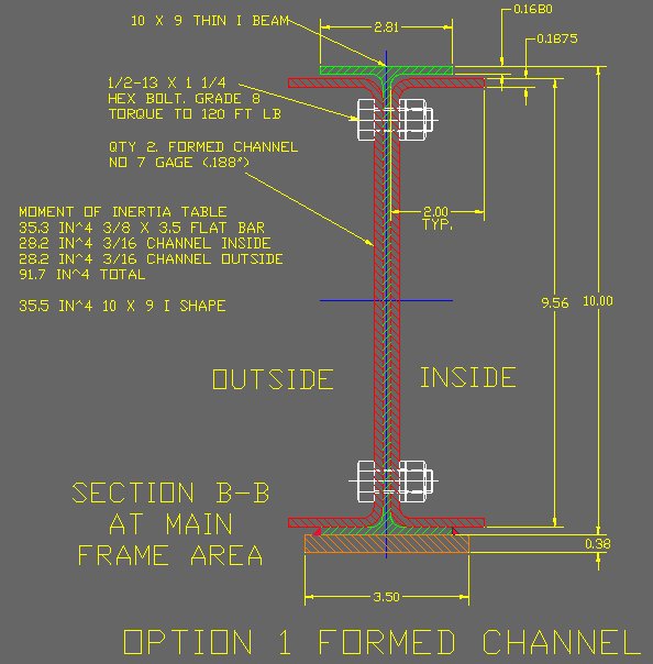
While this made the splice plate area very strong, and maybe too strong. It did not help the bent beam become straight. The formed channel is 60" long and had to fit almost exactly between top and bottom flanges over a bent area of 60". And I have to blend this very stiff section back into the normal flex of the original frame so it would not move the problem to where the splice plates blend back into the original beam. Very stiff joining to very flexible beam issue.
Quote:
Originally Posted by Mrtweety
I do see how these plates nicely incorporate the lower flange of the original beam and tie it together with the sister plate. They also have the effect of stiffening the original beam lower flange to resist lateral bending.
|
Exactly. I picked Option 2 out of the 3 options.

Option 2 allowed me to create the repair method and sequence of the repair. The saw cut fix was part of getting the bent beam back to a level of straight that was usable that I could control in my shop. It also cut out the bend stress in that area. It did however add back some weld stress. The splice plates now can be less taller then the ID of the beam itself and being 60" long, still fit inside the original beam flanges which are no longer straight.
The needs where also to strengthen the lower flange and to make the whole cantilevered frame stronger. And help the blend area from stronger sections back to the original frame. The qty 2, 3" angled plates on the side of the bottom flange create both a lower flange anti-buckling effect and they make the flexing of the lower flange to the web stronger. All of the lower flange flat bars are full length of the frame from the center equalizer to the end of the frame. This up's the strength of the original frame over all and lowers the very stiff splice plate area back to the original frame concern.
The bottom flange plate was part of the lower flange repair, create more anti buckling effect and boost the whole beam strength. It being the farthest from the neutral axis, I gain a lot of inertia for little weight. If you look at the MOI numbers, that bottom 1/4 x 3.5 wide flat bar adds as much inertia as one of the sister plates at less weight.
Quote:
Originally Posted by Mrtweety
I've seen these plates used on other campers where the spring hangers are attached I presume for just that reason.
|
The spring hangers.... yes, these thin I beams have very little strength in flexing of the lower flange. All you need to do is put a 12" adjustable wrench on it an pull medium force and you can bend it. Think of what the side forces are doing during a 45 degree turn going down the highway on tandem axles? That tire scrubbing is pulling on those hangers.
I added my angled gussets and cross hanger supports a long time back as my hangers where flexing and I bent one turning around in my driveway. Some folks have cracked the web from the hanger flexing. This is an industry issue, not just Sunlines. Lippert even sells a parts kit to fix the older frames with the web cracks.
I expanded on this fix when I created the full length 3" flat bar method.
Quote:
Originally Posted by Mrtweety
I also see how you are using them to weld / secure the final assembly in a low stress natural state. What other thoughts did you have on these lower plates ?
|
The plates once I make it through the welding process, (which is tricky with the camper on top) I have high hopes will help cure the problem. I gain both strength of the old and new beam area, I gain anti buckling, they help blend in the splice plates strength to the old beam and I gain much lower flange flexing. The stabilizer jacks may even gain some anti wiggle of the camper... that is just a perk of a side effect.
Thanks
John
__________________
Current Sunlines: 2004 T310SR, 2004 T1950, 2004 T2475, 2007 T2499, 2004 T317SR
Prior Sunlines: 2004 T2499 - Fern Blue
2005 Ford F350 Lariat, 6.8L V10 W/ 4.10 rear axle, CC, Short Bed, SRW. Reese HP trunnion bar hitch W/ HP DC
Google Custom Search For Sunline Owners Club
|
|
|
|
|
02-27-2017, 08:18 AM
|
#63
|
|
Junior Member
Join Date: Feb 2017
Location: Pennsylvania
Posts: 6
SUN #9104
|
John,
Thanks for the insight and taking time to share your knowledge. And after all this ......to think the Lippert Field team was just going to stress the beam back and weld a few plates on the bottom. Creating in effect a "spring loaded beam" that is just waiting to bend down again. Really makes you wonder....
BTW Pam and I were looking at some old Sunlines again. They were masters of the basic trailer but fell off a bit it seems when they tried slide rooms and 5th wheels. Kinda like the old VW beetle after 1970 when they were forced to put emission crap on it and attempted the "auto transmission" Both were a disaster for a great simple design.....
Steve
__________________
|
|
|
|
|
02-27-2017, 03:41 PM
|
#64
|
|
Moderator
Join Date: Nov 2006
Location: Ohio
Posts: 12,654
SUN #89
|
Hi Steve,
Glad to help and yak anytime...
The RV industry has gone through an evolution for sure on how to build a slide out room. Sunline in many areas is better then many other brands. Even still since they ended in 2006.
Yes, the slide adds a level of extra things to work with/through. In my case, I will have a real tough time talking my better half back into a non slide camper... She wants her room!!! And I like it too, just I also like the non slide campers, the pop up and even the tent too... Every RV show I go to or even when wondering a RV dealers yard, my head is under the camper looking at the slides, frames and suspensions...
The VW bug.... yes that was unique. My step dad use to have a car repair garage back when independent garages sold gasoline. He would pick up used cars often, fix them up and sell them. He had a 68 vintage I think VW bug once and brought it home as a daily driver for a while. Amassing gizmo... An air cooled engine with heat ducts along the lower rocker panels just above the running boards.... About froze to death in the winter in upper NYS. And that engine sound... it is a unique sound never yet reproduced.... They sold a bunch of them. Herby the love bug lives on... The reinvented bug just never caught on.
Thanks
John
__________________
Current Sunlines: 2004 T310SR, 2004 T1950, 2004 T2475, 2007 T2499, 2004 T317SR
Prior Sunlines: 2004 T2499 - Fern Blue
2005 Ford F350 Lariat, 6.8L V10 W/ 4.10 rear axle, CC, Short Bed, SRW. Reese HP trunnion bar hitch W/ HP DC
Google Custom Search For Sunline Owners Club
|
|
|
|
|
02-28-2017, 04:15 PM
|
#65
|
|
Moderator
Join Date: Nov 2006
Location: Ohio
Posts: 12,654
SUN #89
|
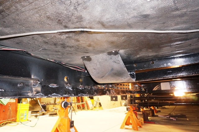
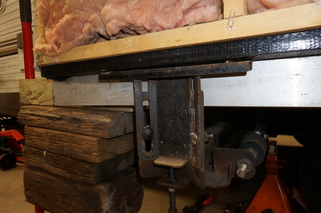
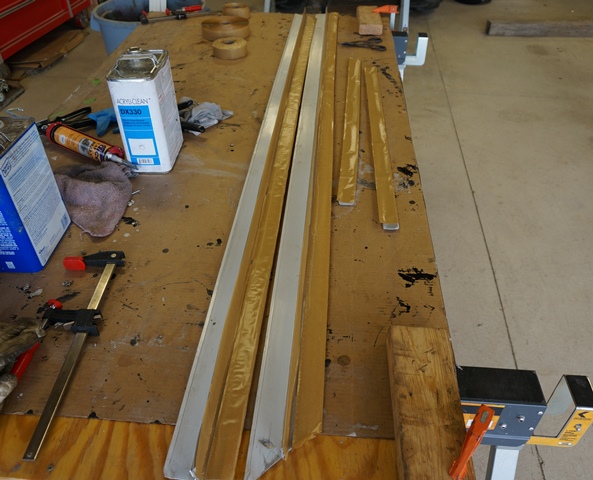
Some more progress. All the lower flange reinforcement steel has been fitted, weld prepped and today, weld tacked in place. I have not yet completely decided if I am going to add a second 3/16” flat bar on the bottom of the flange. Originally this was a single 1/4" thick flat bar. When I could not get the 1/4" short of getting a mill run, I changed it to 3/16”. But I also manipulated the side angle pieces too to keep the area moment of inertia up. I can add that second bottom piece if I need/want to after. I’ll see how many issues or not the first one is coming out of the complete welding process and weld shrink.
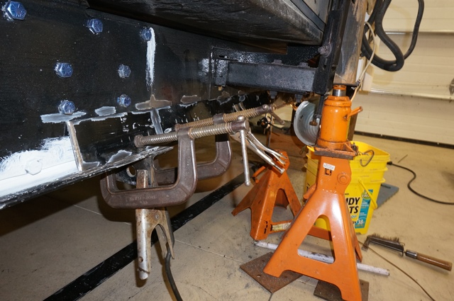
Here is the first part of the fit up. The areas where the welds will go are wire brushed clean. It looks sort of yucky on the paint job, but that will be redone after all the welding is over.
The first longer rear section on the outside, all prepped to be weld tacked.

A close up.
A view of the rear end of this section

The shorter add on piece of this area to take the reinforcement all the to the equalizer.

And the end result at tacking up the plates. No more clamps… I used this wire brush wheel on the end of the 4 1/2" grinder and it does an outstanding job of getting slag or anything else off the welds. I also use this to beat off the paint prepping for the weld.

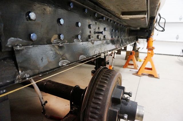
Here is the inside and outside all tacked in place ready to start final welding planned for tomorrow.
A pic down the length of the outside
The rear area of the inside
The center area of the inside

The front area of the inside up to the equalizer area.

More as the progress continues.
Thanks for looking
John
__________________
Current Sunlines: 2004 T310SR, 2004 T1950, 2004 T2475, 2007 T2499, 2004 T317SR
Prior Sunlines: 2004 T2499 - Fern Blue
2005 Ford F350 Lariat, 6.8L V10 W/ 4.10 rear axle, CC, Short Bed, SRW. Reese HP trunnion bar hitch W/ HP DC
Google Custom Search For Sunline Owners Club
|
|
|
|
|
03-05-2017, 12:03 PM
|
#66
|
|
Senior Member
Join Date: Sep 2006
Location: Ontario
Posts: 503
SUN #43
|
Quote:
Originally Posted by JohnB
Hi Bill,
Thanks for the good words. Much appreciated.
For sure, check your frame. Especially look at the lower flange for "any" type of deflection, bend, twist or anything that is not true straight. Your 5'er floor plan and mine are very close to the same in regards to the rear living area camper. The overhung loads on the frame may be similar. From my rear spring hanger to the back of the frame where it attaches to the bumper is 102" as Sunline provided. (this is not my rear boxes included) And your slide is most likely hanging back like mine with a good amount on the cantilever beam area.
I seem to recall Gary saying one time, Kitty and his 5er had the factory couch in it that the weight an immense amount. Theirs was a full pull out bed I think. Does yours still have that couch? I know you changed out the swivel rockers when I last saw your rig.
Look over the whole frame but extra look right behind the rear axle hanger. That is the area that takes the blunt of the force and the lower flange wants to buckle after a towing road "event". If yours has any type of deformation, for sure soon is the time to reinforce this before it continues to ratchet itself weaker and bend down. Then your slide will be like mine....
Let us know what you find out when the time comes. Glad to help share the learning's...
John
|
Hi John,
Yes, our floor plans are very similar and we do have the heavy pull couch in our fifth wheel as well as well as two chairs at the very back of the unit. I will definitely check the frame all over when we can get to the unit and report back. However with that said I have to say with sadness that we made a deal yesterday to trade in our fifth wheel in on a new Grand Design 5th wheel. I am only hoping it measures up to the quality of the Sunline's.
__________________
2018 GMC Denali 3500HD Dually
2018 Grand Design 384GK
Formerly,
2003 F311SR
2005 T-2753
|
|
|
|
|
03-08-2017, 07:10 PM
|
#67
|
|
Moderator
Join Date: Nov 2006
Location: Ohio
Posts: 12,654
SUN #89
|
Hi everyone,
An update on progress. I finished welding the lower frame reinforcement steel on the slide side of the camper. The door side I will do later after I can turn the camper around. There is a sail boat a little too close to the door side to work there. (one too many toys
)
The frame rail came out good. I somewhat feel like a pretzel from going back and forth between the outside and the inside to help balance out the weld shrink pull. All the inside is mostly overhead or hanging sideways. There was 126 stitch welds on the lower flange reinforcement steel to do along with some lower flange repairs and putting on of some brackets I had to cut off. I used up slightly over 4.5 lb of welding rods.
Time consuming but it paid off going slow and watching with the dial indicators to see where any heat shrink was going and how much. There was some, negative cambering Ill call it, the beam bending down and Ill call it minor compared to where I started. Close to 1/16 slight downward at the rear hanger area and about the same 1/32 to 1/16 towards the last 4 feet of the frame. Standard weld tolerances can be a lot more then 1/16, but in this case I was pushing for as close to dead on as I could make it.
The adding rigidity in the frame is very noticeable when you jack up the camper. The camper now lifts with each pump of a jack. Before it would flex, need extra jack pumps to get it to start moving and finally grunt/ flex and go up. It is still flexible, but in a different league.
Here are a few pics, not a lot to see that different, other than weld smoke flash and wire bushing paint scrubbing marks, but just to update you.
A view of the outside frame rail
A view of the inside frame rail.

The inside cross member repaired where I had to cut ready to weld on.
The outside outrigger bolted/welded back on

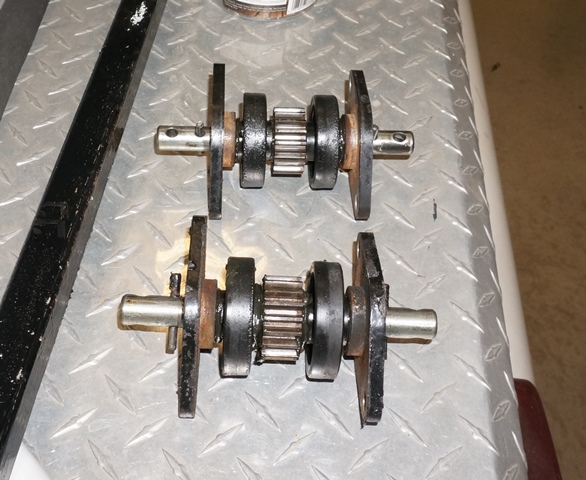
I did rebuild the slide rack and pinion square shaft drive. The bronze bushings in the pinion assembly where worn to the point, now is the time to rebuild them. Here are a few quick pics. I will do a separate post on this rebuild later.
This is the pinion assembly


The wear. It seems the master rack sq shaft drive side wears the heaviest. 0.055 wear ID and uneven. The wall thickness is only 0.060"

And both rebuilt ready to go in. Cost of new bushings from the local hardware store, $4.50. Good for another 13 years of camping.
I have finally made it to putting the camper back together
I have to clean up all the welded areas and repaint. Then onto the slide room and put it back together and get it adjusted.
Thanks
John
__________________
Current Sunlines: 2004 T310SR, 2004 T1950, 2004 T2475, 2007 T2499, 2004 T317SR
Prior Sunlines: 2004 T2499 - Fern Blue
2005 Ford F350 Lariat, 6.8L V10 W/ 4.10 rear axle, CC, Short Bed, SRW. Reese HP trunnion bar hitch W/ HP DC
Google Custom Search For Sunline Owners Club
|
|
|
|
|
03-25-2017, 09:08 PM
|
#68
|
|
Moderator
Join Date: Nov 2006
Location: Ohio
Posts: 12,654
SUN #89
|
Hi everyone,
An update on progress. I have not posted in a while, but progress has been moving forward. There was a week I had a Granddaughter flower and sign building project which was GREAT!!!!  and then another week I bought 2004 T1950 “project camper”. ")
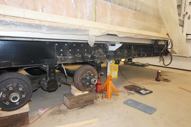
The frame fix is done on the slide side. All the welds have been primed and painted. Now to put everything else back together and readjust the slide.
There was a quantity of little things that had to be remounted to the frame. The shock absorbers put back on, several grounding lugs needed to be drilled and bolted back onto the frame, the BAL stabilizer jack needed to be remounted, mud flaps remounted, some floor to frame braces, put the cross shaft drive for the slide back in and a first in a long time, put the tires back on! YEH!!!!
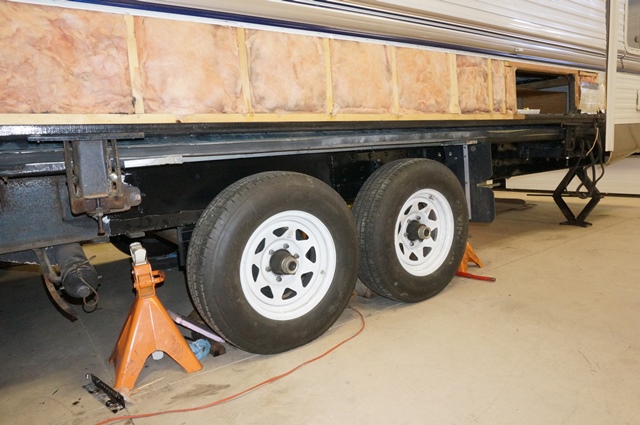

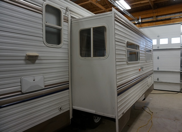
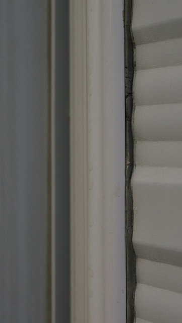
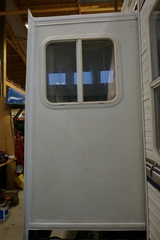
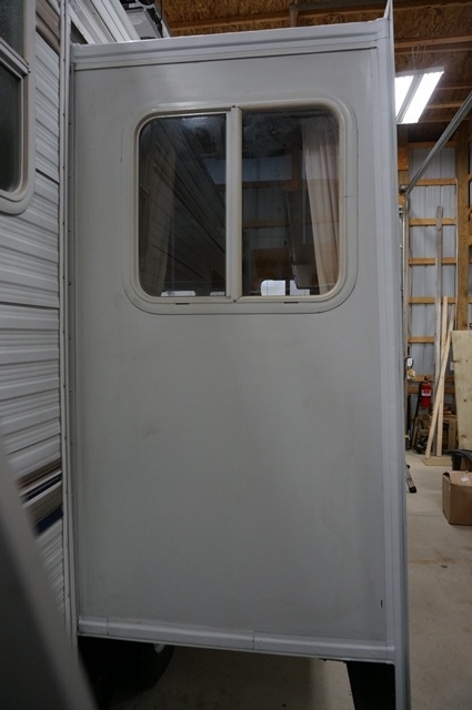
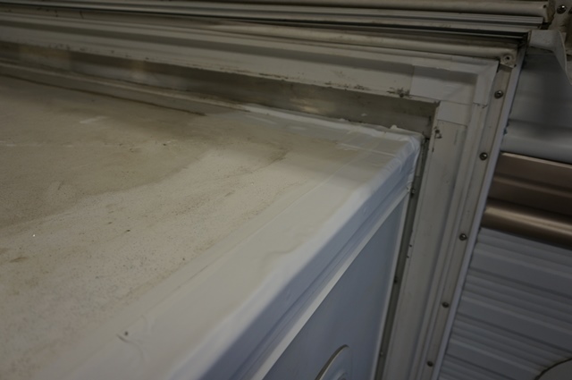
Here is the big deal, is the slide opening square to the slide with the wheels on and no bottle jacks or jack stands supporting the camper? Yes, it is! The camper slide wall opening is about 1/16 to max 1/8” out of square to the slide. The slide itself is not 100% square nor is the slide wall opening, but I am pleased with the outcome. This is a mega difference then where I started.
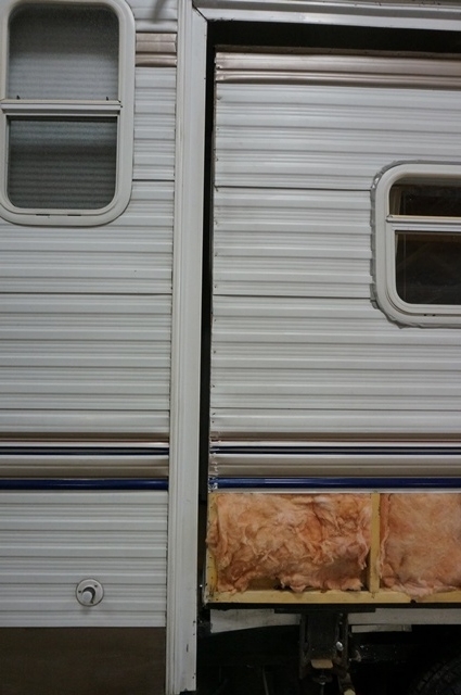
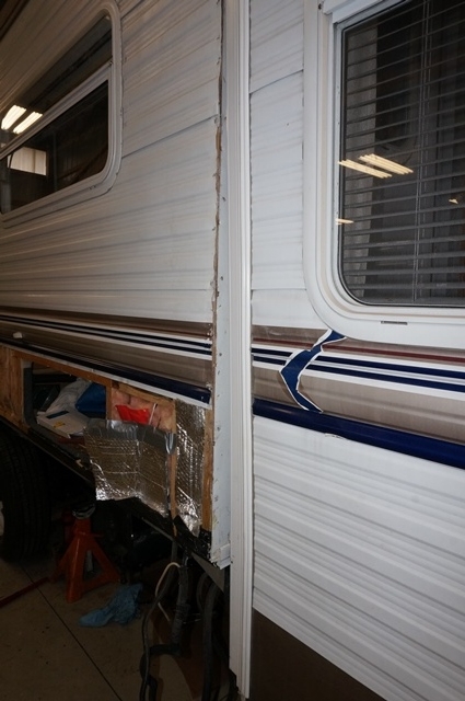
Here you can see the relationship of the slide opening to the side of the slide when closed and when open. The gap is parallel which it needs to be.
Here is the rear slide end

Here is the front slide end
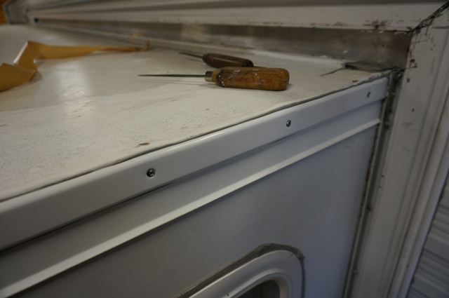
Next is to start adjusting the slide. Since the slide was adjusted to attempt to work in a non-square hole in the camper over the years, I needed to go through a total slide re-align. The first issue is the depth the slide retracts in and extends out. From the day we bought this camper in 2007, the lower rear corner slide flange never compressed tight like the other 3 corners. In fact the slide flange molding was tweaked (bent) inward to make the gasket seal. I tried once straightening out the slide flange but then there a very large gap in the gasket compression so I bent it back. Now that I have the slide apart I can see the issue. I saw this about 2 months ago when I first had the slide flanges off. The rear lower corner is not retracting in as far as the front lower corner and when the slide is extended, the lower rear inside slide flanges do not meet the wall flange even either. When I took the square shaft drive off, this is the first time it has ever been off or unhooked since I owned it. I stamped the shaft for position marking and the slide arms never moved to insure the timing goes back to the correct place it came off. See the slide here
The front lower slide wall is even with the camper wall at the bottom. The stop can on the slide master rack is now tight to the frame.

Now the rear lower slide wall. A very noticeable extension of the slide from the camper.
And here is the slide flanges. The bent one is the lower rear flange I was referring too. The straight one on the left is the front slide flange like it is supposed to be. That bent slide flange is how it has been working all these years.

After seeing this and thinking on it, this slide is a good 1 inch plus off from retracting and extending. It is like the slave drive arm is out of time with the master rack. It has been working this was since 2007, but this is not right. So I pulled the bolt on the square shaft master rack pinion shaft and rotated the shaft 1 hole backwards (retarded timing), 90 degrees of the shaft and put the bolt back in. That 1 hole gained me a lot of the difference the rear slide arm was out. Also learned that each 90 degrees of square shaft rotation is approximately 1 3/16” of slide arm travel. With this much adjustment it will create a problem with the bottom slide seal gasket. There is an aluminum angle screwed to the bottom of the slide floor that clamps against the camper to keep the water out that will now not be correct. By looking at this clamping angle, it is not right either. It is not parallel to the slide floor or the ends of the slide arms. It is a very different distance from the end of the slide arm to the slide mounting bracket. See here.
This is the front slide arm. The silver aluminum angle is up tight against the slide arm mounting bracket.

Here is the rear slide arm. The silver aluminum angle a good 1/2” plus away from the slide arm mounting bracket and the bottom slide seal is not compressed. Now I am convinced this timing issue was from the factory miss as this clamping angle has never been moved.

For the timing being, I unscrewed the clamp angle so I could finish adjusting the slide travel.
The square shaft timing took care of most of the issue of the rear lower corner being not flush with the camper. There is a separate adjustment on the slave slide arm to fine adjust between a square shaft hole rotation. The end of the slave slide arm has slots and you can push or pull the slide where you need to go.
See here. The slots are on the 2 vertical bolts on the end of the slide arm, the slots are hard to see.
Here is a top down pic showing the slots

To do this adjustment, I clamped a piece of metal as a reference 1” away from the slide arm end so I can measured how far I moved the arm.
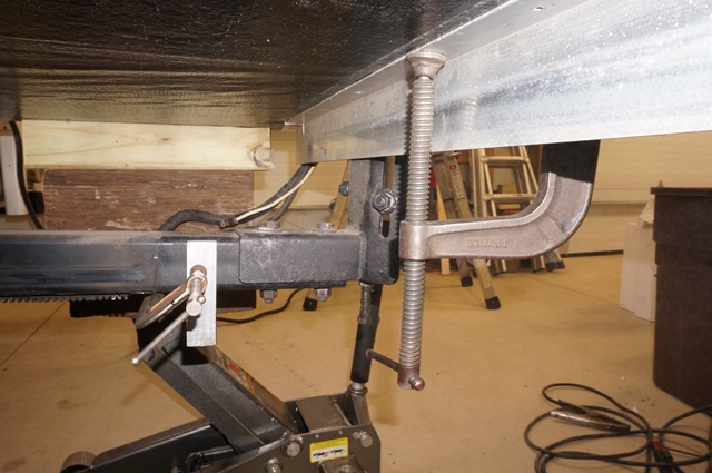
Then you need to lift this end of the slide and push or pull the slide where you want it. I jacked up the rear end of the slide room and I loosened the bolts. Then pulled the slide out approx. 1/4” and tightened up the bolts. You can see I clamped the aluminum angle temporally in place.
Now to test the slide in and out. I had to remove the bottom seal clamp angle before moving the slide all the way in. Sure enough now the rear side is closing flush and extending flush. This most likely was off from day 1 at the factory. They were just 1 hole off. I never had the square shaft apart and the bottom seal clamp angle was screwed on in location when the 1 hole of location was.
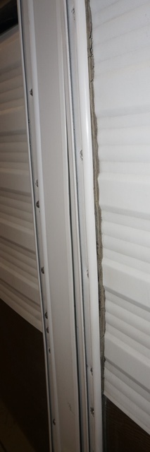
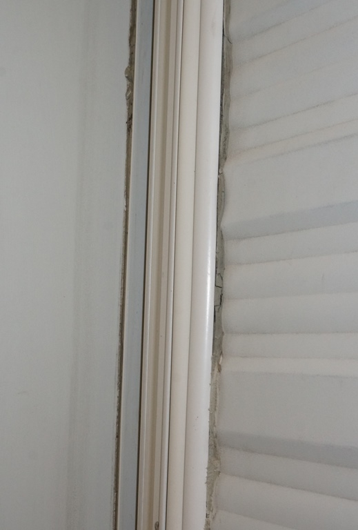
See pics now with the front and back flush when closed. The rear side

The front side

This completes the extend and retract until I get the slide flanges on. The stop can may need to be adjusted once the slide flanges are put on and the slide seal is installed. However the slide room is now extending and retracting even on both ends of the slide.
Next is to center the slide room in the middle of the camper slide opening. There are slots in the slide arm mounting brackets that bolt to the floor.
You can see here the yellow zinc bolts at the slide floor area and that the slot is all the way one way. This was how I was able to get the slide to work by skewing the slide over on the tight fitting side. Now I have to get it more centered.
First I needed to fix the bolts that clamp the slide room to the slide arm brackets. On this 2004 camper, Sunline used carriage bolts from the top down inside the wall. The issue with carriage bolts is over time the bolts rust outside and the threads are all rusted up that are exposed. Then if you attempt to unscrew the nuts, the added drag from the rust allows the carriage bolt heads to strip in the soft wood and then you’re stuck…. I had to cut the bolts off as there is no way to clamp the bolt and get a nut off of a rusted bolt. Since I had the wall apart I changed this bolting setup. I created a plate that I could tack weld the head of a bolt to so it would not spin in the wall.
The tack weld is not on yet, the screw to hold the plate to the slide sill or the final black paint. You can see the 2 plates installed. The rear slide arm has this too. I will grease the exposed threads which are already zinc plated so they do not rust up

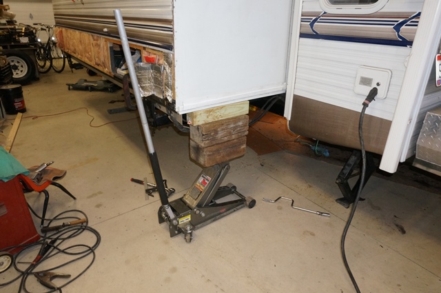
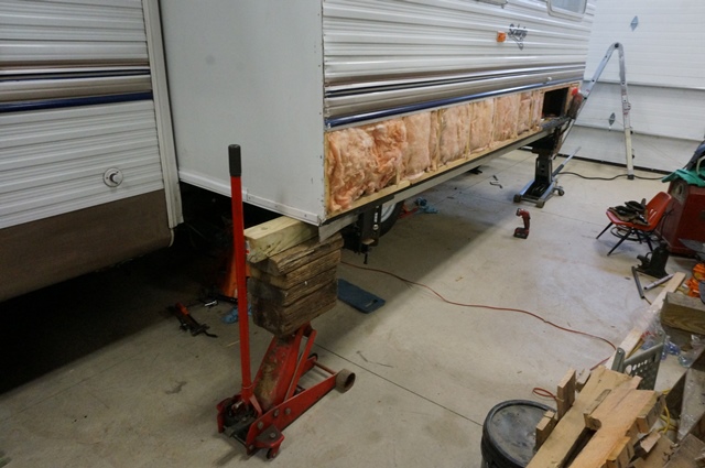
Then to lift the slide at both end and push or pull the slide front to back of the camper to center it. I used 2 floor jacks with wood cribbing on the end walls.
Before you move the slide, you need to loosen the slide arm brackets and lift the slide enough the slide arms are unloaded. You can see the gap between the slide floor and the slide arm bracket. You need to do this to not try and bend the slide arms, you want to move the slide on the slide arm bracket.
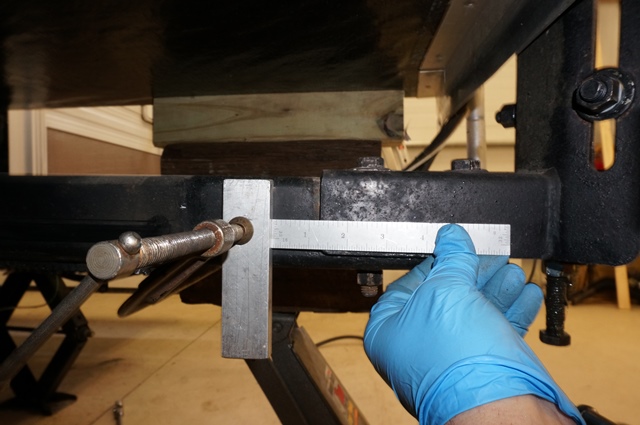
Before moving the slide, measure the distance is on each end. This is so you know you are actually moving the slide and not deflecting the slide arm. This distance needs to change the amount you want to move the slide.
Front end

Rear slide end

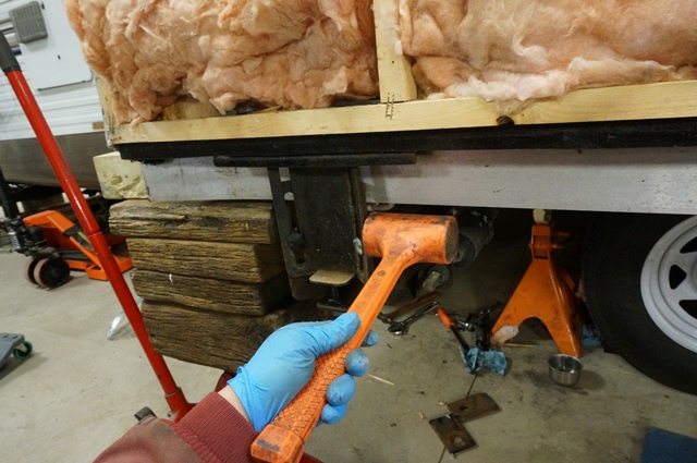
Now to move the slide. While the jacks have a lot of the weight off, the part in the camper is still touching the floor. It takes a good push to move it. I had to use a pry bar in the right location and it move easy.
Here is the location at the side of the slide at the bottom where the floor is at it is very strong here to pry against.

I used a wood block to protect the slide and put the pry bar up against the camper slide flange. A little tug on a 3 ft pry bar and it shift over. Tweak until the slide is centered in the camper opening.
Then you have to check that the slide arms are in the middle of the arm housing welded in the camper frame. Mine was drug all the way to one side with the slide move. I needed to tap the arm back so there is equal clearance between the slide arm and the nylon wear pads at the red arrows.

A dead blow hammer hit and it move over to center in the slots.
Once the both arms are centered and the slide is centered in the camper, you tighten up the bolts to the slide arm bracket. The reason you need the arms centered on the nylon pads is so that naturally the slide is positioned where you want it and it is not being forced by the slide arms. If the slide arms are under pressure from being pushed to one side, after enough moves of the slide, it will move to try and relive that binding pressure. So get rid of any bind before your start.
Here is the slide now all centered and aligned to this point. The gap at the red arrows is even and the same as the front of the slide.

This is as far as I can go until the slide flanges are installed and the slide seal put in to finish up the slide alignment.
The weather temperature is now cooperating and allowing me to do things that need 60F and above like rubber roof glue. The next post is on fixing the slide roof damage caused by the out of square situation.
Thanks for looking. More soon.
John
__________________
Current Sunlines: 2004 T310SR, 2004 T1950, 2004 T2475, 2007 T2499, 2004 T317SR
Prior Sunlines: 2004 T2499 - Fern Blue
2005 Ford F350 Lariat, 6.8L V10 W/ 4.10 rear axle, CC, Short Bed, SRW. Reese HP trunnion bar hitch W/ HP DC
Google Custom Search For Sunline Owners Club
|
|
|
|
|
03-26-2017, 10:07 PM
|
#69
|
|
Moderator
Join Date: Nov 2006
Location: Ohio
Posts: 12,654
SUN #89
|
Some more progress to report.
I had some more frame rust scraping and painting to do on the slide side frame rail. I wanted to get all the painting done under the slide area while the slide was still apart. This is now done and 3/4 of the way to the A frame header on the slide side. A fair amount more to go on the entire frame, but that will be after the slide is finished. Frame painting is a “job” for sure…
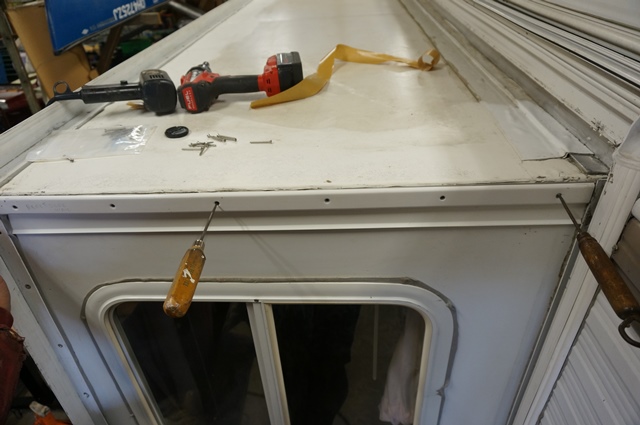
I needed warmer weather to reglue some of the slide roof. Some loose spots showed up on the ends with bubbles and some was affected when the roof scraped the slide flange on out last campout. These bubbles do not leak or really cause an issue and I would of left them alone normally, but I had the slide apart and not that much more work to correct now, so now is the time to deal with them. Here are some of the bubbles.

I will show some pics of how a slide roof is made up for those who have been ben into one yet. The siding on the long wall of the camper needs to be opened up at the top. You take the staples out of the top siding piece and it will pivot away from the slide. There is a 1/8” filler strip behind the siding on top of the rubber. That is stapled on too. It needs to come off


Next is the rubber itself. It is stapled to the slide frame.
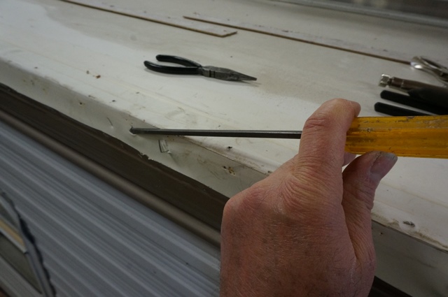
I discovered using a very old tool and a new use for it greatly helped taking staples out of any size. Tiny to the largest on the camper. The tool is called “End cutting nipper pliers” . These have been around a long time. I picked up this pair at a close out sale at Tractor Supply. http://www.crescenttool.com/pliers/c...er-pliers.html
You can buy them direct or at other tool outlets cheaper. They are a quality tool and when they grip a staple, then just pivot the tool to pry them out. While I have the Crescent brand, there are many other brands out there. I use a thin tipped screw driver, work the blade edge under some part of the staple to get it slightly lifted. Then use the pliers to grip it. If you squeeze too hard, they can cut the staple if wanted, I just do enough pressure to grip and out they come. Beats the vise grips hand down and 3 times faster.
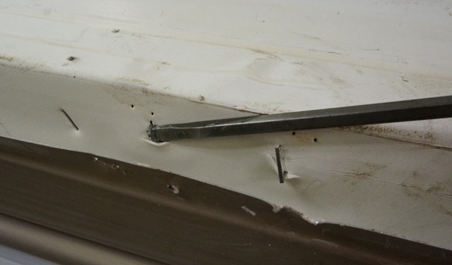

Once the staples are all out.....(a task in itself) then you can lift the rubber where it is loose. It will stop where it is glued well. If you tug, you can lift some more to get a bubble in a short ways.
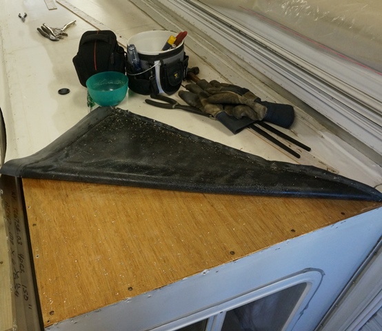
On the ends of the slide, when I would wash the roof, there was always a rough feeling under the rubber like there was dirt or something under it. When I lifted the rubber up, for sure there is dirt under there. And a bunch of the aluminum shavings from the screws at the factory. How they ended up here is a mystery. They may have clung to the rubber somehow or touched the shop floor at the factory and picked them up when they were assembling the slide.
You can see specs, that is debris
A close up

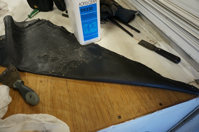
On the slide roof, they used 1/8 luan plywood to glue the rubber too. Then to get the old glue off the rubber and the luan was the next task. A tedious job but I found a few chemicals that would help. On the luan, mineral spirits rubbed in by a rag to break the bond and loosen the glue so you scrape it up. It comes up in goo balls in globs.
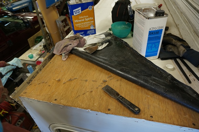
The rubber, the mineral spirits did not seem to work as well or fast. I switched to the PPG DX330 cleaner and it worked much better. You use a large enough rag the end can be dipped in the cleaner and rubbed on. Then the dry part of the rag helps the scrub and remove the glue. This chemical works fairly fast so do not let it soak. It also evaporates fast. I kept pushing in one direction to sweep the glue globs all one direction. It worked well.
You can see the difference between clean and still glue residue
Here are a few more pics of the process. Rub on the end of a rag the cleaner pushing in one direction. It will loosen the glue and start to roll up. This is a ruff cleaning.
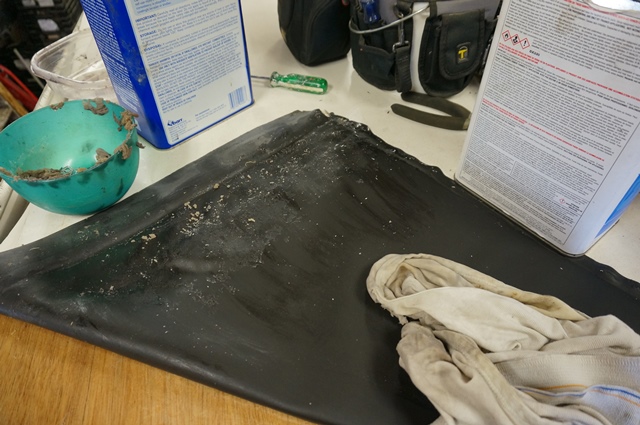
Then wet the rag some more with cleaner and rub a second time. Now the left over residue rolls up at the end.


I have used a polished end very dull, with no sharp edges putty knife to scoop up the globs. This is what the globs look like. They stick to everything.

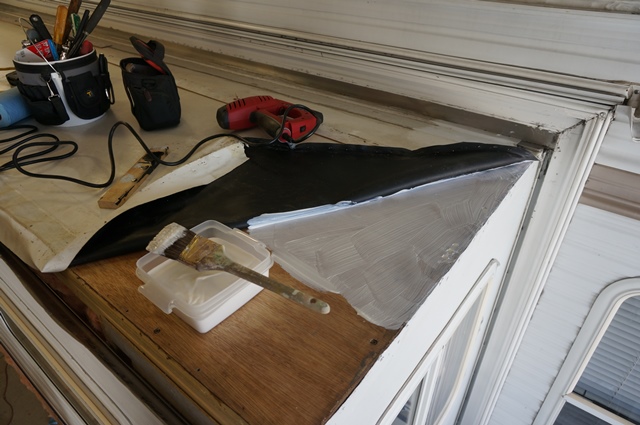
Here is the whole slide cleaned up in what needs to be reglued

Then you need a day when the temps are above 60F to put the glue on. We had 2 good days back to back at 70F. This is water based glue I am using. Dicor 901BA bonding adhesive.
You brush or roll it on the luan, not the rubber and you do the entire area. It needs to be fairly heavy coat as it will absorb some into the wood.
Once the adhesive is all on, you go right to folding over the rubber and smoothing it out. Gently working out any air bubbles. You do not want to push too hard to squeeze out the glue, just firm enough to make sure the rubber is fully contacted with the rubber.

Then you pull gently, not to stretch the rubber, but make it snug and staple the ends and the long side of the rubber to the slide frame.

I had a few bubbles that had been in the roof a long time. The rubber sort of stretched at these locations and had a memory to keep popping up. I had a few smooth boards and some weight to put on top to let it setup with the bubbles held down. It worked OK, the next morning I only had 3 small bubbles left and I could push them down now that the glue was more tacky to hold them down.
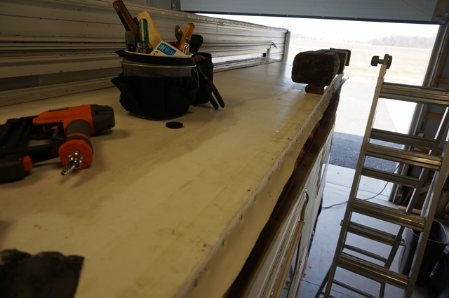
Next is to staple back on the 1/8 filler strip

And then staple the top siding piece on. These air staplers work great!

So the roof gluing is done and onto the next items.
More tomorrow.
Thanks
John
__________________
Current Sunlines: 2004 T310SR, 2004 T1950, 2004 T2475, 2007 T2499, 2004 T317SR
Prior Sunlines: 2004 T2499 - Fern Blue
2005 Ford F350 Lariat, 6.8L V10 W/ 4.10 rear axle, CC, Short Bed, SRW. Reese HP trunnion bar hitch W/ HP DC
Google Custom Search For Sunline Owners Club
|
|
|
|
|
03-27-2017, 08:27 PM
|
#70
|
|
Moderator
Join Date: Nov 2006
Location: Ohio
Posts: 12,654
SUN #89
|
Another update on current progress,
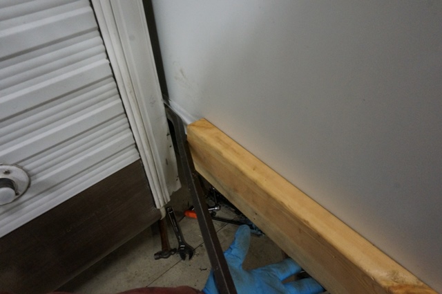
One of the fender boards had some rot in it. Water made it's way in a hole in the Darco waterproof membrane. These fender boards are Darco covered OSB boards living in a very wet location with water flying off the camper wheels when towing in the rain. Since I had them off with the siding, I decided to upgrade these to pressure treated plywood. These fender boards attach to the bottom of the slide and allow the lower gold siding to attach. They also act as sort of a fender so to speak, but ahead of and behind the wheels. They extend and retract with the slide. They are below the camper floor line.
I want to also report on a new tool my 2 children and DW chipped in an gave me these for a Christmas present one year. A saw guide for the circular saw. I do not use these all the time, but when you need to cut up a 4 x 8 sheet of something, they come in very handy. I have an 8’ 3” one and a 50” one. This brand, e-emerson-tool-co.
I now see a number of more generic ones of these on the market.
This guides are great!!! They have an internal clamp that is easy to use and clamps tight on a 4 x 8 sheet of plywood that holds very rigid and the guide is thin enough the circular saw passes right over it. They make quick and accurate work of a sheet of plywood into smaller pieces.

The above treated plywood re-created the OSB fender boards. They start out cut to size then Darco wrapped and stapled. The Darco jointed side is positioned on the very outside. The non Darco jointed side is towards the wheels. In the case of treated wood, having a hole in the Darco is not as devastating as with the OSB. A hole in the bottom can now let the water out and not rot the wood.

Once they are all wrapped up, I also cleaned the Darco of any dirt etc. beforehand. Then taped the seams over the staples with Gorialla tape. I warmed the tape areas with a heat gun and then rolled it to insure the adhesive set. I have found the heat and press trick with this tape enhances the adhesion.

Here is where they attach to the slide. The slide floor is made so when the fender boards mount, they are flush with the outside wall.

Here they are mounted now ready for siding.


Next to put the siding back on. Here is the first piece on.

Then the lower gold pieces.

Then the cargo hole door unit.
For folks who want more info on cleaning up and mounting siding, cargo door, windows etc, see this post with more details. http://www.sunlineclub.com/forums/f7...tml#post131768
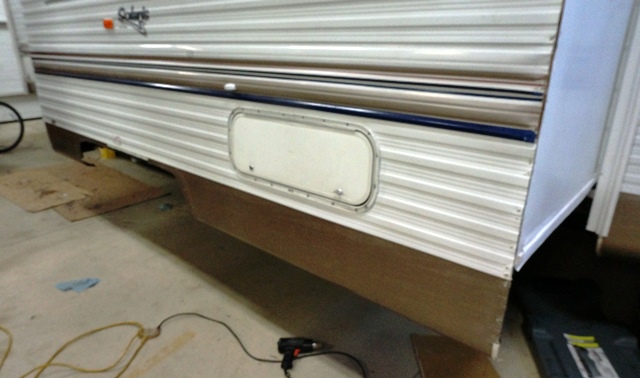
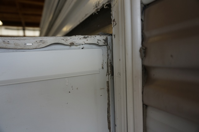
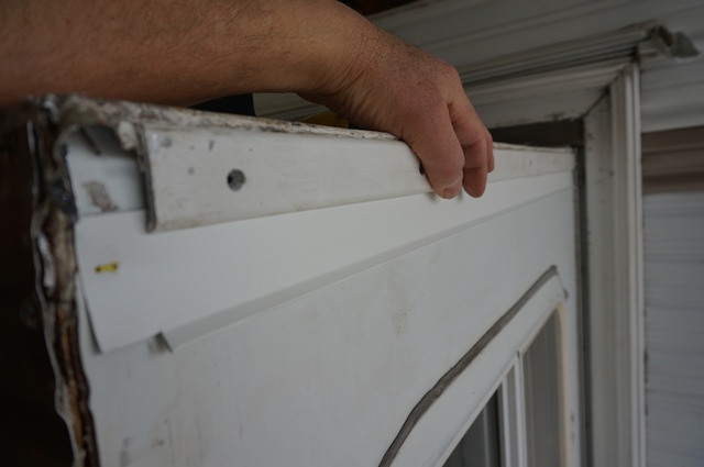
The next area was to make a drip edge above the 2 slide side windows. I do not yet have a slide topper awning and as such, water beats down the side of the slide in a heavy rain. During the slide frame sagging time frame, the back of the slide was lower than the rest of the camper and during a heavy rain, a lot of water would come off the back of the slide and run down the wall. It would beat on the window frame putty tape seal between the window and the slide wall. During the 2015 Midwest M & G at River Trail CG it rained so hard, water came in the window unit somehow. We were in the camper at the time and caught it running down the inside wall and mopped it up. When the monsoon stopped, I made a make shift Gorilla tape gutter above the window to deflect the heavy water running. It got us by, but I knew long term I had to do something better.
When I had my slide floor rot years ago due to running water on the side of the slide, I made a drip edge at the slide floor area to deflect the water out away from the camper rather than being able to wick under the slide. That drip edge works great so I used the same concept here.
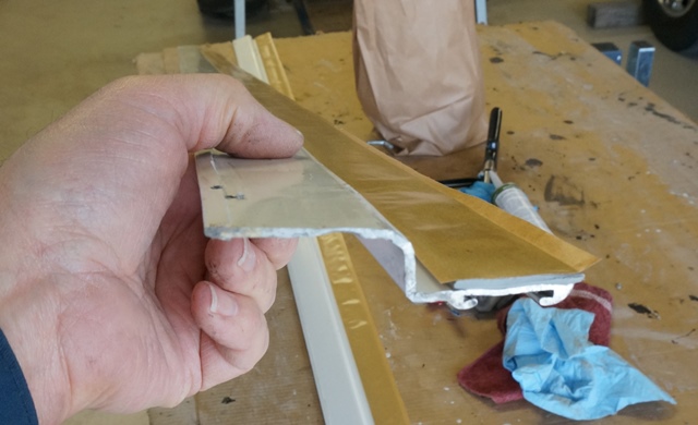
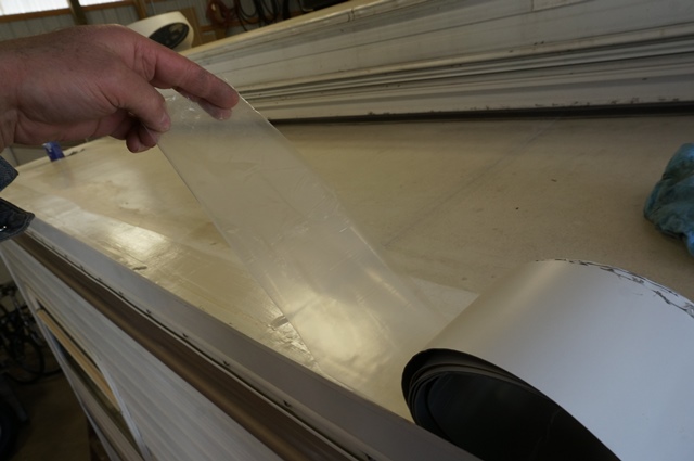
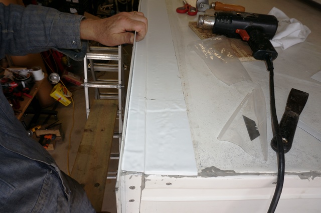
You start with large leg drip edge that you use on a house, barn etc. I get the kind with the drip edge that is hemmed. The edge is folded over onto itself and makes all smooth edges to not cut the slide seal. They do make cheaper drip edge without the hem but it will cut the slide seal. This 10 foot piece only cost $5.90 at the Menard’s. A mega big box store in our area. It is 2X of a Home Depot and they even sell groceries….
The drip leg is much longer on this style then the standard drip edge and that was what I was after.
Here is the drip edge hemmed edge I was talking about
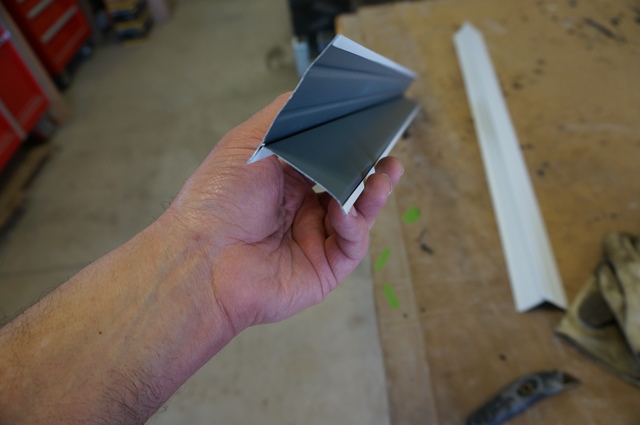
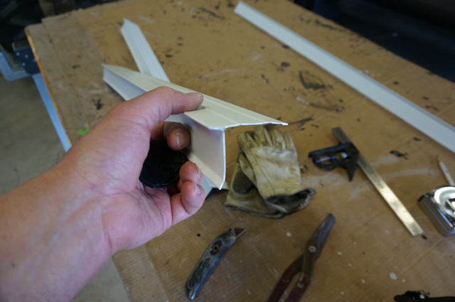
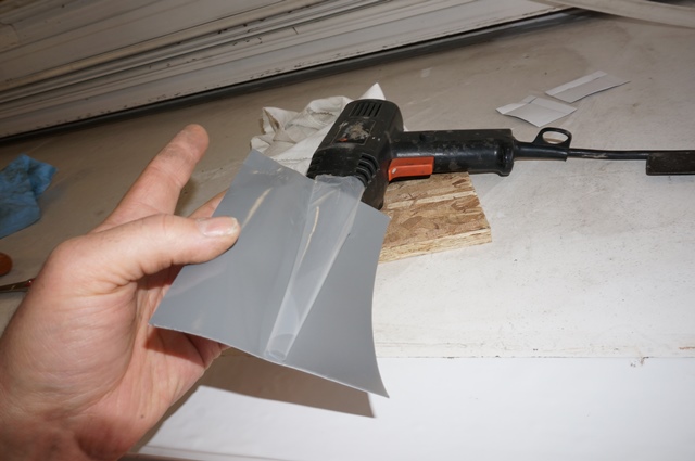
Next is to slit off the drip leg from the shape. Using a method I learned from from doing aluminum siding work on houses, you score the aluminum and then fold/crack it along the score. Start with a new blade in a dry wall utility knife. Score 2 times on the corner the full length. Have full support under the part you are slitting and use gloves.

Once slit, then fold the drip leg flat against the drip edge top piece.

Then, fold it back over 180 degrees on itself and it will crack right along the slit line perfectly. You have to slit deep enough for this to crack on the back fold.

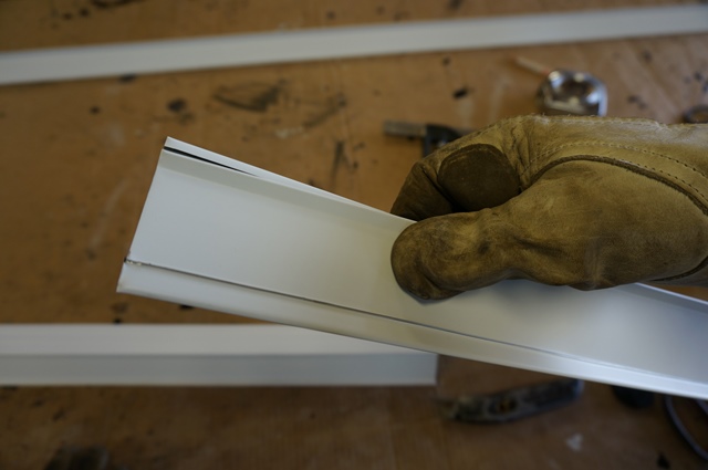
Now I have 2 nice flat white aluminum drip edges for the top of the slide. These will mount at the top of the slide. When the water runs over the slide end molding, it will follow the drip leg down like it does on the normal side wall. When the water reaches the drip edge, it will break up the water flow path and deflect the water away from the top seal of the slide window. What was there before was a leak waiting to happen with the slide tipped downhill all the time. Granted now the slide is fixed, but I have this all apart fixing the slide damage so it gets the upgrade.
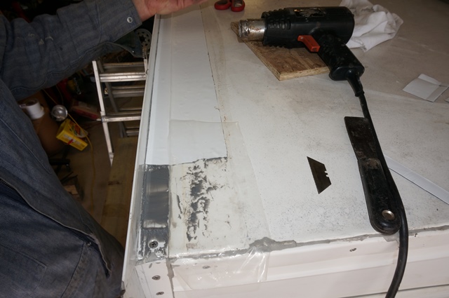
The drip lip piece attaches here. I insert the drip edge strip into the putty tape at the slide flange area which will be behind the slide out seal. The the other end into the new butyl tape area of the slide corner when I install the corner. Two staples holds it in place until the slide cap molding goes on with butyl tape.
I trim the drip edge to allow it to slide into the putty tape
Here it is inserted and stapled

The corner molding will fit like this. The drip leg is trimmed and stapled under the corner molding area.


Here is the slide top cap molding mocked up that will be filled with butyl tape and put over the rubber at the end of the slide and over this drip leg strip.
Since the rubber at the 90 degree corner has a few damage holes from the slide damage due to the out of square situation, I will cover this area with a piece of Eternabond tape after all the molding is in place.
Next is to put all the slide flanges on, the top slide molding strips and Eternabond all those areas. More in the next few days.
Thanks for looking
John
__________________
Current Sunlines: 2004 T310SR, 2004 T1950, 2004 T2475, 2007 T2499, 2004 T317SR
Prior Sunlines: 2004 T2499 - Fern Blue
2005 Ford F350 Lariat, 6.8L V10 W/ 4.10 rear axle, CC, Short Bed, SRW. Reese HP trunnion bar hitch W/ HP DC
Google Custom Search For Sunline Owners Club
|
|
|
|
|
03-30-2017, 08:57 PM
|
#71
|
|
Moderator
Join Date: Nov 2006
Location: Ohio
Posts: 12,654
SUN #89
|
Next update, Mounting Slide Flanges and Trim.
The good news, I continue to have less and less parts to put on…  This time the pile of slide flanges and trim get installed. Between the windows, cargo doors, slide flanges and trim I have applied and cleaned up over 150 feet of butyl tape…
I have converted to all stainless screws a while ago when doing any repairs. My son found this lead for me, https://www.albanycountyfasteners.com/. They have good service, quality, a large selection and the pricing is good. Buying stainless screws in the little bags in the big box stores or hardware stores is cost prohibitive if you need any kind of large quantity. Only thing ordering here, is planning ahead to allow for the shipping time. Shipping is free for orders over $35.
To note, we have converted to the no. 2 square bit drive in place of hex and Philips where ever possible. This has worked out well.
Reusing the old flanges and moldings is the cheapest solution, however it takes a good quantity of time. The old flanges have to be cleaned up and then straightened. After this, then installing is about the same time as installing new flanges.
A few tips we have learned in applying old flanges in the same place is to use 1 or 2 ice picks as hole alignment. This helps set the flange you are mounting right back in the same place. Most times you want to use the same placement and other times, on purpose you want to move the moldings to correct a problem. The ice picks help on both as they can pierce the siding and still hold the molding while you work to mount it.
The heat gun is your friend, even at temps daytime temps. of 50 and 65F. They help warm the butyl tape to flow easier while you are torqueing down the screws. It does not take a lot of time, just warm the flanges with the butyl already on them before tightening the screws. The ice picks hold the flange, then warm it, then screw in the screws.
Here are some of the slide flanges ready to install. You leave the release paper on until the last moment as this butyl is very sticky.
Here are the ice picks in action
In some cases, it helps to start all screws, just leave them apprx 1/4" to 1/2" or so before tightening. Then you know all screws align and the molding is in the right location.

Then warm with the heat gun and set the screws. In this case, using a portable drill with a slip clutch set on low can help as you do not over torque the screws. I have also found the portable 1/4" impact which ratchets as a certain torque can be used. You just have to stop at the right time. More skill is needed with the impact to not overdo it, but it does work well. You can see the warm butyl ooze slightly out. This is later cleaned up.
I also converted the slide flanges from hex heads which stick up with sharp edges to flat heads. And in this case Albany Fasteners does not have square drive in flat head of this no. 8 size. So we use the Philips. The reason I converted here and countersunk the screw heads, the hex heads cut through the slide tape Sunline put on and then they started cutting into the slide seal. Now the surface is flat and makes putting Eternabond on come out nicer as it lays flat. The excess butyl in this pic still needs clean up.

Now all the slide flanges and moldings are mounted. The corner moldings and the top moldings have screws on both sides of the 90 degree corner. This makes a very strong corner and flange. The flange is under a good amount of load when the slide has compressed the slide seal gasket against the camper. There are so many screws in the corner that it does not affect the corner being stripped off. The design works well.
Here are some pics of the moldings all cleaned up and ready for the Eternabond to be applied.


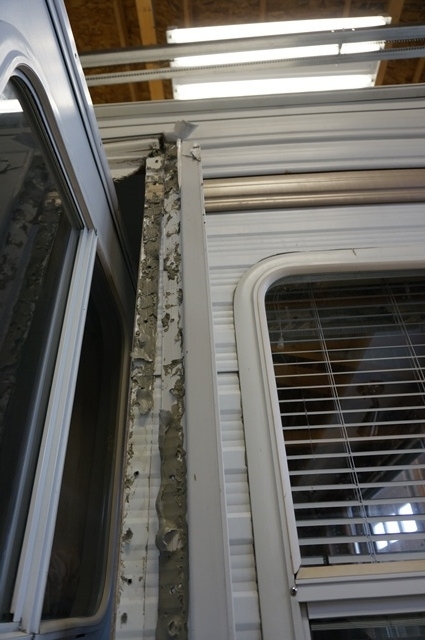
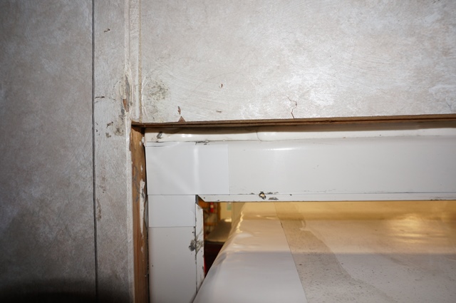
I “thought” I was ready to start the Eternabond process and then I looked at the putty tape on the slide flanges mounted to the camper. These have never been off before. They have been on since Nov. 2003 when the camper was made. And the putty tape started rearing its ugly head. 13 ½ years later, cracks are starting to be numerous in the putty tape.
Now decision time, there are only 2 more flanges (what is another 14 feet of butyl...) , you have the slide seal out and the time, do you just take them off and replace with fresh butyl? I have been on a mission over the last few years to replace all the windows and entry doors putty tape with new butyl and I’m about 3/4 done. Well…what not replace? So I did and after seeing behind them, glad I did.
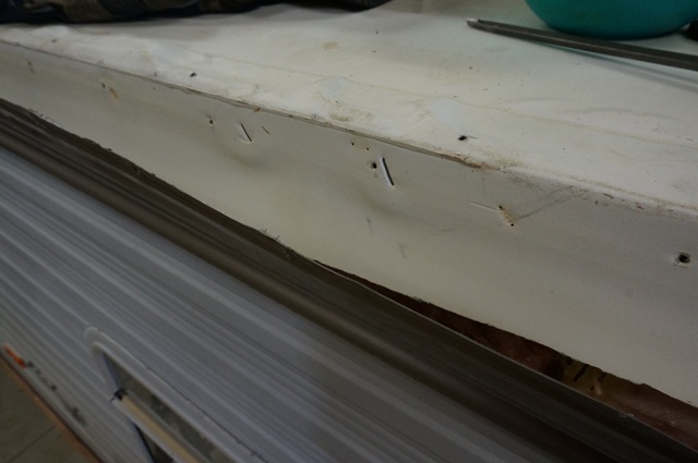
The front and back camper opening slide flange showed a different appearance. Here is the front. You can see the putty tape has become separated in places from the siding or the flange as dirt has been driven into the joint between the molding and the siding. If this passage gets deep enough, water can beat into the camper and infect the wood.
This is the front flange turned over and placed next to the area it came off. The black areas are dirt driven into the joint from what I believe has come from towing in the rain or wet conditions.
The upper area

The bottom area

A close up of the dirt area on the bottom

A note to report, while the dirt marks do indicate a path for moisture to get in, all the screws that came out of this flange had no rust on them. The problem did not yet advance enough. I do not really know how many years it takes to create the water infiltration issue from a side separation of the putty tape. How much one tows with the camper verses being on a seasonal site and then towed in the rain is a variable. Is the molding protected from roof water or is it directly under a gutter spout, was the camper stored inside most of it’s life or outside, how old is the camper, how good was the quality of the putty tape when applied are only few of the variables. Our camper lived outside from Nov. 2003 until Sept. 2013. Almost 10 years. And we have towed the camper a fair amount. I have not added up the mileage recently, but I would estimate around 35,000 miles, maybe 40,000 by us. I do not know the mileage of the prior owner for the 2 years they had it.
Now to the rear slide flange area, this one had different signs. Here are some of the putty tape cracks from the outside


Here are a little closer

Here is a very notable picture. Every screw from this flange had rust on them all the way to the end. Not good.

However the dirt marks like the front flange had do not show up.
Here are 2 closer shots. It does now show up well, but there is a slight yellowing of the putty tape leading up the screw holes in certain areas. This “might” indicate there was an air passage from separated putty tape. OR, this yellow area is held tight due to the screw in the area and the light gray area is an air passage way? I do not know exactly. Some how water made its way to the screw. Now seeing this, I wish I had pushed a very thin feeler gage in one of the cracks to see just how far it would go.

Where my finger is pointing is a suspected putty tape separation from the flange. The dirt staining points to this.

I “think” the reason we do not see the black moldy dirt in this joint, is the location. The slide room itself protects the molding from rain driven in from towing forwards. The front flange is in the line of fire of the water flying down the side of the camper when towing and runs into the slide flange molding. The rear flange, the exposed edge is protected by the molding itself. Since we do not tow in reverse at highway speeds… water does not get jammed into this rear molding. However it is under a gutter from the slide roof molding area. That may be part of where the rusted screws came from or at least one larger factor.
At this point, need to move on and replace the putty tape with quality butyl and move on. Scraped off all the old, cleaned up the flanges, straightened the flanges, and put new butyl tape on. These flanges are wider and they take a full 1 1/4" wide butyl and does not leave any excess.

As FYI, this slide flange is different than the ones on the slide that have a square corner joint. They look like this.

I fill each corrugation of the siding with strip of butyl to fill any questionable voids. This does use more butyl but I am after making sure the seal is 100% and will stay that way.

These 2 slide flanges are now all mounted and cleaned up. I need to put Eternabond in the top miter corners and on the flanges to cover the screws as a next step. More on this in the next post.
Thanks for looking.
John
__________________
Current Sunlines: 2004 T310SR, 2004 T1950, 2004 T2475, 2007 T2499, 2004 T317SR
Prior Sunlines: 2004 T2499 - Fern Blue
2005 Ford F350 Lariat, 6.8L V10 W/ 4.10 rear axle, CC, Short Bed, SRW. Reese HP trunnion bar hitch W/ HP DC
Google Custom Search For Sunline Owners Club
|
|
|
|
|
03-31-2017, 08:18 PM
|
#72
|
|
Moderator
Join Date: Nov 2006
Location: Ohio
Posts: 12,654
SUN #89
|
Today I finished up putting the Eternabond on the slide. I still have some caulking to do on the exposed edge of Eternabond sealant, but putting down all the sealing tape is done.
This time I used a new type of primer for the Eternabond. Eternabond sells 2 types, a spray can type that I have used before and a liquid you brush on. This time I used the brush on as I can control where it goes better. It worked really well. This primer really enhances the stick of the Eternabond which is already very sticky. I would classify the primed surface to be considered, sticky on steroids… If the E bond tape touches the surface even slightly, it’s stuck…
This is the primer product I used, in the quart can https://www.eternabond.com/EternaPri...ternaprime.htm
Here a few things about using it. It is a very thin clear liquid. It has a viscosity about the same as kerosene. I believe it is considered a solvent resin. They list many breathing hazards and not to breath prolonged vapors. So I just put my respirator on and had no issues. The metal bowl in the pic is what I poured some resin into for the brush and then put the bowl in a container so in case it splashed or dripped it did not get all over. This resin gets very sticky during the drying process. Once dried, it is not very sticky to the touch but is extremely attractive to the Eternabond sealant. It takes approx. 20 to 30 minutes to dry before applying the sealing tapes. To clean up your brush or get it off of the bowl, tools etc., lacquer thinner worked well. They listed other solvents too.

I have used Eternabond before. For those who want more in-depth use of this on your camper, see this post. http://www.sunlineclub.com/forums/f7...ics-11610.html
I’ll touch on the high points here. The first thing is the surface needs to be cleaned. This is a must. I used the PPG DX330 as I use this for other cleaning. It is a high flash cleaner, does its job and evaporates quick to not affect the rubber and does not hurt the Krystal Kote on the siding or the white paint.

You can also use a cleaner from Eternabond, called Eternaclean. It is in a spray can. This works/smells like brake cleaner. I also noticed today this new can will take the Krystal Kote off the siding if it gets on there. I do not recall this from years back. This is not an issue on the roof or the white metal flange, gutters etc. aluminum. They also list acetone as a cleaner, however acetone will melt off the camper white siding paint and the Krystal Kote. So be careful if use acetone.

Once cleaned, primed and the primer dried, you start putting the Eternabond Roof Seal tape down. This takes a getting use too and here some tricks I learned along the way on how to deal with something so sticky. There is a silicone release paper on the back of the tape. Here is a trick, save some of the release paper as a starter tool to get the new tape put down. You create your own along the way but have none to start with. Unless you create a scrape piece of tape to start with.
These are the basic steps to dealing with putting Eternbond down. Cut the piece to install first off the roll and trim it as needed as much as practical before putting it down. Do not have the whole roll in your hand, it is too clumsy and will cause issues getting stuck where you do not want it.
You peel a very small amount of the release paper back. And you touch just one corner edge to stick it while holding the tape high up off the surface. I recommend until you get going, to put your spare release paper over the primed surface except the touch down spot where you are starting to prevent too much accidental sticking at once. Once the full width is attached for an approx. 1/8 to 1/4" of running length, then you can start the next process of undoing the release paper off the back.
You can see here, I have the release paper that already was peeled back on the first foot of tape being put down, lying flat over the primed area. And the tape with no release paper removed held up in the air.
You then peel approx. 2 inches of release paper back and hold the tape up high enough and tight to not touch the surface. Here I am holding up the tape taught while the 2” of release tape is under this area.

Then you touch the tape to the surface with one hand while the other holds the tape tension taught. As you move your fingers the sticking will stop once you reach the release paper. Then after about 6” of applied tape, you go back and roll the tape to the roof. Eternabond needs pressure on the sealant to create the bond to the roof, metal etc. Lack of pressure will not allow a bond to be made and an air pocket may develop over time.

To keep going, you repeat the pull off about 2” of release liner, touch it down, roll and then pull some more until you are done. In this case I was using 4” wide tape and on an uneven surface. The slide flange molding was approx. 3/16” higher than the roof. In this case I touch the higher surface first while keeping an air gap on the lower surface. Once the upper surface is all touched down, then I would roll over the step to the lower surface. Then wipe out the lower surface. As you get better at this, you can increase the release liner pull from 2” to 3 or 4”. Going to 5 to 6” can be very tricky on uneven surfaces. The odds are not in your favor you can keep 6” taught enough to not have an accidental touch down of a loose flap of tape in the wrong place creating a massive wrinkle.
This is all about keeping wrinkles out of the tape. Once the tape touches, it’s stuck. If it lays down in a wrinkle, it is there to stay. You really cannot smooth out a large wrinkle. You can however, cut out the wrinkle and stick it back together.
Here is another trick on undoing a goof…. When I started this long section, I did not have any excess release paper to help get started. And I had forgotten how aggressive primed surfaces are…. When I started the tape run, I peeled the entire 4” width (this was OK) but I also peeled 4” in running length. This is too much to get started. The 4” of running length without release paper should have been 1/8” to 1/4" with no extra release paper.
See here, my goof. You can learn from this. This is after I cleaned up the mess
Since I peeled too much release paper before the tape was stuck down to start, the flap towards the camper, flapped and touched the roof in the middle. This made a major wrinkle to start with. You can see the upper surface of the slide flange is bonded well as all the adhesive is still there. To get yourself out of a “goof”, the first thing is to “Stop!” as soon as the goof happens. You are not going to smooth out a very large wrinkle and you have 2 choices, slit the wrinkle, take out excess material and then press down the edges to seal it back up. This creates a wedge effect and does not look good and in this case does not seal over what I need it too.
So you go to the next option, completely remove the messed up piece. The trick to Eternabond is knowing how to remove it. The heat gun is again your friend. If you heat the tape and use a scraper, the adhesive turns to a hot goo and comes up. The heat will break a sticking bond when you are pulling on the tape. This is what I did. I slit off the bad material to make a clean repair and I took off the messed up tape and then applied good tape on the area.
To help explain the repair, you start with a new short piece to cover the area. Put down a section of used release paper over the major area you do not want yet to stick. You can see it here on the roof area. The release paper is clear but you can see a reflection of it laying on top of the good white Eternabond already put down and the primed roof area.
Then I started the patch and only peeled the one end to stick to the high side of the upper slide flange area.
Then align and touch the upper area. The release paper is still on the patch and the old spare release paper is still in place.

Then remove the spare release paper and fold down the step edge to the roof level. Then pull about 1” on the release paper and smooth it down. Then keep doing the pull and press until the whole patch is down. Then roll it and your fixed.
Here is the whole length of the slide on the outer slide flange

This is what I did for the corners miter joint. This joint is never tight and Sunline used butyl slide tape on this area on a 45 degree to cover the whole joint. I repeated this 45 degree patch when I had the slide fixed for slide floor rot several years ago. I did not like the outcome of the Eternabond repair using that method. Too many different surfaces to work the tape around and it created too many wrinkles. I used this approach this time and it came out very well. It is 2 over lapping straight pieces creating the 90 degree corner.

Here is a test cut and fit. No stick down yet. This is the first corner piece to put in

Test fit here

Then the 2nd top piece, here is the folded tape piece

And test held for a fit check

And here is the installed and stuck result. Sorry this is the rear slide side, I missed a pic of the front

Then to deal with the upper miter. I created a patch for it

Test fit

Press on and done

And here is the inside of that joint. Same 2 overlapping square sections.
Here are some pics of the other areas finished off.
Front top slide short side seam


Rear slide wall, all screws and butyl tape covered on the slide flange molding.
Front slide wall, all screws and butyl tape covered on the slide flange molding. And a patch put in on the lower wall molding that the prior Eternabond was damaged with the out of square slide movement.
A couple clean up items.
You can see here a shine of excess primer on the rubber roof next to the Eternabond tape heading along the long wall side of the slide. I need to wipe off that excess primer as it will allow dirt to stick to it. My PPG 330X will take it off as I tried it and I will try just lacquer thinner too for those who do not have the more costly PPG product. And I need to apply a film of Dicor caulk to the small exposed edge of the Eternabond as dirt will stick to that small exposed sealant. The side seal will also in time grab it. The Dicor smear of caulk will seal it over and it not be a problem.
That is all for now. More in the next few days.
Thanks for looking
John
__________________
Current Sunlines: 2004 T310SR, 2004 T1950, 2004 T2475, 2007 T2499, 2004 T317SR
Prior Sunlines: 2004 T2499 - Fern Blue
2005 Ford F350 Lariat, 6.8L V10 W/ 4.10 rear axle, CC, Short Bed, SRW. Reese HP trunnion bar hitch W/ HP DC
Google Custom Search For Sunline Owners Club
|
|
|
|
|
04-08-2017, 08:10 PM
|
#73
|
|
Moderator
Join Date: Nov 2006
Location: Ohio
Posts: 12,654
SUN #89
|
Hi Folks,
An update on progress. I’m gaining…
I finished up the Eternabond sealing. There is an exposed sealant edge with Eternabond that can attract dirt and become sticky. On a building roof, this is a non-issue. On a camper, it can be detrimental especially on a slide. That exposed edge of sealant, even though it is only about a heavy 1/32 thick, can get stuck on the slide seals. To correct this issue you need to put a small film of Dicor non leveling roof sealant on the exposed edge and smooth it out. Apply a very small bead of Dicro and spread it smooth. I use the soapy wet finger trick. Put 3 drops of Dawn dish soap in about 8 oz. of water and just keep your finger wet and the caulk will not stick to it. Wipe your finger on a rag after each swipe and then re-wet and go again. Works good.
Here are some pics showing no exposed Eternabond edge sealant. The caulk is hard to see as everything is so white, but it’s there.


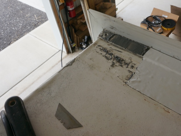
Next was to get back to the rest of the frame rust. Everything forward of the axles needed to be done. Scrap, wire brush, prime and top coat. This is when a small camper comes in handy....
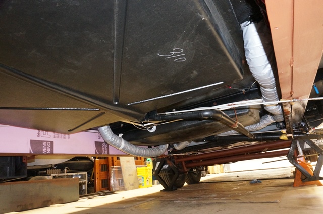
This Sunline travel trailer has enclosed heated holding tanks. This was not a normal option that could be ordered but I was lucky enough to end up with it. It may have been a special order or a prototype. The larger 5th wheels have this, just normally not the travel trailers. For those who have never seen a Sunline enclosed tank setup, you can see some of it here along with the frame priming.
This is just behind the A frame header. There is an approx. 5 foot section which is not enclosed. You can see the start of the tank compartment where the pink insulation board is. Yes, there is a roll of wiring hanging down, more on that in a bit.

Here is the start of the front area of the tank compartment looking towards the axles.

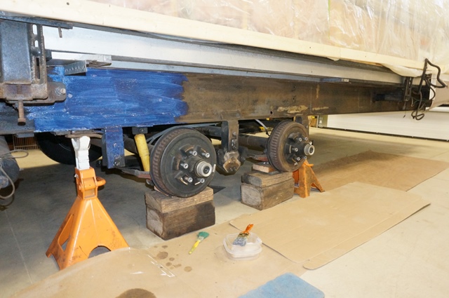
Here is the axle area. The fresh tank and protective cage under it is right over the front axle. This location does not affect the tongue weight in this location. A good thing as we do carry fresh water to many camps.

There is a coroplast cover which goes on the bottom of the tank compartment. What is coroplast? Coroplastâ„¢ Sheets - Corrugated Plastic Sheets | Regal Plastics It looks like plastic cardboard. Many RV manufactures use it for underbelly covers on enclosed tank setups. It is totally water proof as it is made out of plastic, light in weight and not that expensive. It however has some characteristics to it that are a draw back. It droops/sags down over time, water can wick into the end flutes of it near the axle area from towing in the rain and it can crack.
Years ago I added Reflectix foil insulation Reflectix History 101 | Reflectix, Inc. to the top of the coroplast cover. This helps allow me to go lower in outside temperatures. I also installed an air temperature sensor in the tank compartment so I can see what is going on. I needed to redo the tape holding the reflectix to the coroplast sheet. Gorillia tape was not available when I first did this and I redid all the edging with it. This holds the insulation in place while you put the cover on and it keeps the water out of the flutes when towing in wet conditions. The cover was cleaned, the tape was warmed and the tape rolled to enhance the sticking action. Here is it ready to go back on.
The exposed outside bottom side

Here is the reflectix attached to it.


As you can see, this tank cover is almost as long as my truck. It is somewhat of a beast to get on and off but I managed to create a process that is tolerable and I can do it by myself.
There are 3 extra left to right supports I added. A 1 1/4" x 1/2" thick pressure treated wood strip with a piece of 3/4" IMC conduit with stainless steel hose clamps holding it together. I walked the aisles of the lumber yard until I found something strong enough, light, not that expensive and came up with this. Here they are primed. These have worked well for many years now and they show no deterioration. Back by the axle area, I have cross supports welded in-between the spring hangers for strength at the hanger area and they keep the cover from dropping no lower.

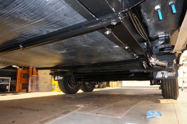
After the priming, comes the black top coat of Rust-O-luem Pro black.

The tank cover on

Now to that roll of wire hanging down. Years ago I rewired the brakes to have an independent no 10 awg wire upgrade. This helped greatly get full power to the brakes from the truck brake controller. However back then, I still used the frame ground as a source of 12 volt DC (-) negative for the brakes. All the coil wires came to a junction box and one main wire went to the frame ground. Over the years I questioned myself, why didn’t you run a no. 10 awg 12 volt DC negative from the 7 wire cord to the brake junction box in the back? Good question, I should have and now I know exactly why.
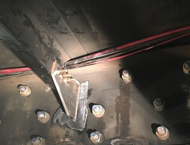
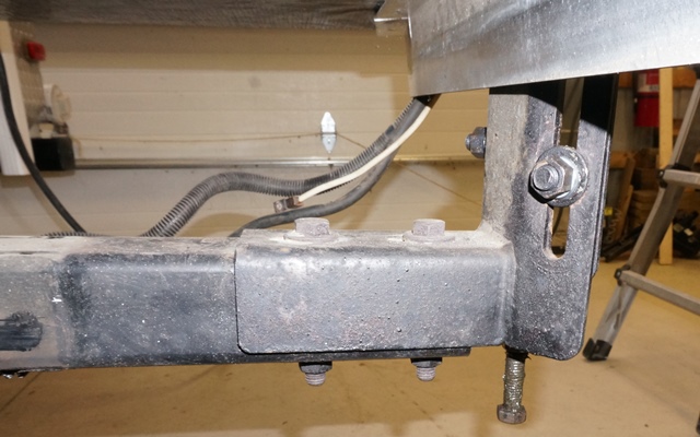
Here is how my camper frame is grounded for the 12 volt DC negative. The large heavy white wire out of the header is the DC negative off the battery. It feeds a bare aluminum buss bar screwed to the header. The buss bar being screwed to the header creates the chassis ground and used for the 12 volt DC negative. The other large heavy white wire from buss bar goes to the ground the LP gas pipe. The gas pipe never wants to have current flowing through it so it has a separate heavy ground wire.
Here is the setup.

The gas pipe ground

Now the problem. The trailer brakes have a direct wire as 12 volt positive from the brake controller in the truck to the brake coils. However the DC negative on the brake coils goes to the trailer frame chassis ground in the back of the camper. This is common practice on many if not most trailers. To add to this, my DC negative from the battery to the power converter which is in the back of the camper, is from a frame ground in the back of the camper.
This all works, however there is a pitfall to using the chassis ground for a brake circuit, corrosion. If you lose the frame ground from corroded connections, you have no brakes or less brakes and the power converter also no longer has a DC negative from the battery if the corrosion is at the buss bar. Or as bad if not worse, the gas pipe has the ability to start acting like a power conductor if it has continuity to the frame which odds are high it does.
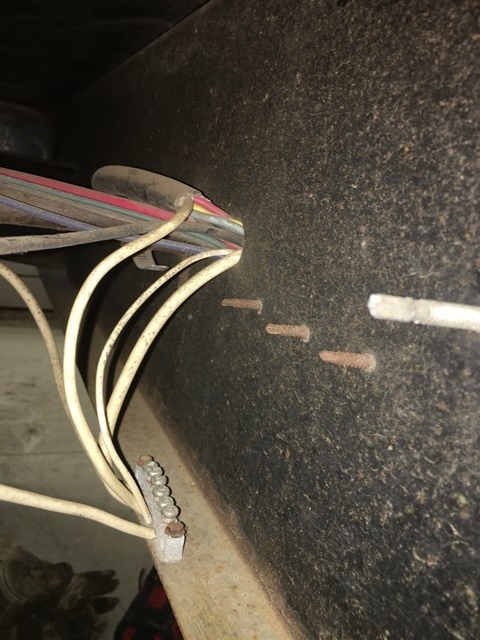
When I touched the screws on the buss bar to take it off, they disintegrated from just putting the wrench on. The bottom of the bare aluminum buss bar had heavy corrosion on it to the steel frame.

This is not a good situation when corrosion gets in the way. This will get corrected which is where the spool of wire comes in. The new no. 10 awg ground wire from the brakes will run direct to the buss bar, I will update the mounting screws to stainless and create a better situation with the frame corrosion issue at the aluminum buss bar to the frame.
I have done other small cleanup things on the slide side of the camper, fender skirt is back on, all mud flaps on, new vinyl screw covers on the slide flanges, a new bottom slide seal installed and a new main slide seal gasket installed.
Here are a few pics of the lower slide seal and the main slide gasket. I will do a separate post on just the slide seals as we do not have one of them yet with pics.
Old next to new bottom slide seal

Old bottom seal removed and cleaned ready for new

New bottom seal installed

Box of new main slide gasket seal

Rear side slide seal installed

The corner joint

Doing the top of the slide
This is all for now. I am hoping in the next day or so to totally finish the slide side of the camper and I can pull the camper out of the barn, turn it around and start on the door side frame reinforcement and the last part of frame painting, (the door side outside frame rail and the trailer tongue needs painting yet) and figure out if I need to reset the entry door since I fixed the frame sag. I’m getting closer to getting this repair done. Yeh!!!
Thanks for looking
John
__________________
Current Sunlines: 2004 T310SR, 2004 T1950, 2004 T2475, 2007 T2499, 2004 T317SR
Prior Sunlines: 2004 T2499 - Fern Blue
2005 Ford F350 Lariat, 6.8L V10 W/ 4.10 rear axle, CC, Short Bed, SRW. Reese HP trunnion bar hitch W/ HP DC
Google Custom Search For Sunline Owners Club
|
|
|
|
|
04-09-2017, 08:33 PM
|
#74
|
|
Junior Member
Join Date: Feb 2017
Location: Pennsylvania
Posts: 6
SUN #9104
|
John - Fantastic work
1. Where did you get the slide gaskets from? Are these std?
2. What do you use for primer? And for final black paint?
We know how you take the rust off - cause you showed us that process with drill and wire brushes earlier.
Steve
__________________
|
|
|
|
|
04-10-2017, 07:50 PM
|
#75
|
|
Moderator
Join Date: Nov 2006
Location: Ohio
Posts: 12,654
SUN #89
|
Thanks Steve,
Some answers to your questions.
Quote:
Originally Posted by Mrtweety
John - Fantastic work
1. Where did you get the slide gaskets from? Are these std?
2. What do you use for primer? And for final black paint?
We know how you take the rust off - cause you showed us that process with drill and wire brushes earlier.
Steve
|
The main upper slide gasket, the one I am using now is from Steel Rubber Products out of North Carolina. Steele Rubber Products - RV and Camper Parts I really like the quality of their product. However it may not be the final seal, but I may leave it. I am gathering a few more pics and there will be a whole post on slide seal replacement and the different types of rubber and slide seals. Through a lot of searching I have not yet found the exact original brand Sunline used which has unique properties to the rubber itself. I'll get that post up in a few days.
The bottom seal, that one has a story to it too, but I am very happy with what I ended up with. It is a neoprene rubber sponge rubber type of seal with very good adhesive backing. This one took a while to find. And oddly enough it comes out of the UK, but showed up in 2 days shipping time. They must have a warehouse here in the states. They are called Rubber Stuff LTD https://www.rubber-stuff.com/. I bought it through Amazon https://www.amazon.com/gp/product/B0...?ie=UTF8&psc=1
The primer and final paint.
On the back of the camper, from axles to bumper, I started by doing a real good job of removing almost all the rust. But there was still rust there, just not as bad as I started. There was some bare metal as well. After cleaning the frame with a degreaser to remove any dust,grime etc. I used Eastwood Rust Converter. Eastwood Rust Converter | Rust Converters | Auto Rust Converter
This chemically converts the rust and stops the corrosion action. This is what it looks like untouched

Then wire brushed, scraped and cleaned and started the converter process. You can see here the camera flash reflects off the wet converter. The unwet area is what I wire brushed the heavy rust down too.
And after it finally cures, it looks like this. Which is a combo of converted rust and bare metal. The acid in the converter seemed to give a rust tint to the bare metal.

Since I had a mixture of converted rust and bare metal, I used Rust-O-leum Professional white clean metal primer over the surface. It is for bare metal and light rust. Professional White Clean Metal Primer Product Page

I then top coated with Rust-O-leum Professional high performance black enamel. http://www.rustoleum.com/product-cat...tective-enamel

After seeing the reaction from the Eastwood converter on the mixture of rust and bare metal, I did the front half differently. The converter seemed to need solid rust with no bare metal to work well. I think I took too much rust off...
On the front, everything forward of the axles, I wire brushed, scraped and cleaned the frame with a degreaser to remove any dust,grime etc. There was minor bare metal areas from the power wire brushing and there was prior painted surfaces not yet rusted. This time I used Rust-O-leum Professional rusty metal primer. Professional Rusty Metal Primer Product Page
Looks like this

I really like this rusty metal primer. It goes on really well and covers and bonds to the metal. Today I was using a file to scrape the paint off to get to bare metal for a grounding lug. Wow, I had to really work at chiseling away through the black top coat and more so, this rusty metal primer to get to bare steel. At this point I feel better about the rusty metal primer then I do the Eastwood converter unless I have a total rust situation.
I then top coated with the Rust-O-leum Professional high performance black enamel. This is really good enamel. Industrial level. It is not up there with the catalyst needed type paints, but when cured it is really good, hard and chip,scratch resistance. The Professional series is better then the standard Rust-O-leum that is still good.

The Rust-O-leum Professional is $32 a gallon on primer and like $39 if I recall right on the enamel in our area. They are both oil based paints and you can only use acetone to thin it. And the application temps are all the way down to 32F if you need to. Brushes clean up well in mineral spirits.
The Eastwood is a water based product. It's strange, I had some brackets that where not loose, but solid rust and the Eastwood did great on them. And I did not even wire brush them, just degreased. It seems the Eastwood needs all rust to work right. The metal was at 55F, the instructions stated 50F minimum. I do not know if that had an effect or not. I can chisel through the Eastwood easier then the rusty metal primer.
I sense your new camper, when you acquire it, is going to need a frame paint job of some type. Need to get it up off the ground ideally so you have some room to move under there, and for sure, wear safety glasses. Years ago when I was doing the T2499 frame, a drip came down and I am sure glad I was wearing glasses.
Hope this helps
John
__________________
Current Sunlines: 2004 T310SR, 2004 T1950, 2004 T2475, 2007 T2499, 2004 T317SR
Prior Sunlines: 2004 T2499 - Fern Blue
2005 Ford F350 Lariat, 6.8L V10 W/ 4.10 rear axle, CC, Short Bed, SRW. Reese HP trunnion bar hitch W/ HP DC
Google Custom Search For Sunline Owners Club
|
|
|
|
|
04-10-2017, 09:15 PM
|
#76
|
|
Moderator
Join Date: Nov 2006
Location: Ohio
Posts: 12,654
SUN #89
|
Today's update:
I cleaned up some loose odds and ends on the back the camper and I corrected the corroded ground lug situation behind the A frame header.
This is what it was.


While that looked good, it is not a good lasting situation. The bare aluminium corrodes, affects the ground between the buss bar and the frame and the wire clamp screws where rusted in place. Using this setup of bare aluminum just does not do well in wet environments. The mounting screws where rusted right through when I took it off

I came up with this solution. Scrap the frame top and bottom down to bare metal in a large area to fit a fender washer. Drill and tap a hole in the header. In my case, 1/4-20 threads. Use 2 large stainless fender washers on the top and bottom of the header with a full thread 2" long 1/4" stainless bolt. I lock washered and nutted the bolt to the frame which is now a grounding stud.
Each wire has an eyelet terminal crimped onto the wire. Do to the bundle of wires to be joined, I separated them with a nut between them to keep it neater.
Bottom view
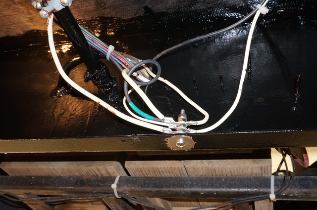
Side view
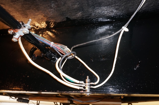
After making all the connections, I coated the terminals and the header area where the fender washers are with dielectric grease to lower the risk of corrosion on the copper plated wire eyelets.
If I was doing this from new, ideally this is all joined inside a junction box. My wire length was limited so this stainless grounding post idea seemed the best with what I had to work with.
By the end of the day I have finished up the slide side of the camper.
The camper made it out of the barn. Yeh!!!! It was a quick outing...

Then, backed in to work on painting the A frame area and prepping to add the lower flange reinforcement steel behind the rear axle to the door side of the camper and sort out the entry door issue.

More in the next few days.
Thanks for looking.
John
__________________
Current Sunlines: 2004 T310SR, 2004 T1950, 2004 T2475, 2007 T2499, 2004 T317SR
Prior Sunlines: 2004 T2499 - Fern Blue
2005 Ford F350 Lariat, 6.8L V10 W/ 4.10 rear axle, CC, Short Bed, SRW. Reese HP trunnion bar hitch W/ HP DC
Google Custom Search For Sunline Owners Club
|
|
|
|
|
04-15-2017, 10:35 AM
|
#77
|
|
Moderator
Join Date: Dec 2006
Location: Pennsylvania
Posts: 2,285
SUN #128
|
What a project! I'm sure Cindy is a happy girl, that you can keep that beautiful Sunline going. Interestingly, the guy who bought the Fox had stopped at the dealer to look at new Arctic Foxes right before coming here. His comment was that our 2012 unit had a better fit and finish than the new ones. He said in comparison it looks like they're slipping up. I hated to hear that since we considered Northwood to be the closest thing to Sunline. There really isn't much out there that Mr. Tweety the engineer approves of. Good you can keep rebuilding what you have.
__________________
Pam
Lance 1475 "Snoopy"
2012 GMC Sierra 3500HD 4x4 D/A
2012 Arctic Fox 30U, SUNLINES - 2006 2753 "Tweety", 2007 QUE "QUEtSE", 2364, 1660
|
|
|
|
|
04-16-2017, 08:54 PM
|
#78
|
|
Moderator
Join Date: Nov 2006
Location: Ohio
Posts: 12,654
SUN #89
|
Hi Pam,
Thanks for the reply. Yes, this has been a "project"... Figuring out the bent frame cause, the fix, putting the fix in and then correcting the damage on the slide from the out of square situation has been a good quantity of work. That amount of work hired out, would of been a very large bill at any reasonable shop rate. The quantity of labor is a huge and needs a specialized set of technicians. The materials are not so bad. This type of repair may have been more then some folks would wanted to invest in a 13 1/2 year old camper. Fortunately for us, I had time on my side to do this and the barn to do it in which makes it easier during bad outside weather. The rest of the camper is still in great shape and still a very high end unit, so fixing this myself was well worth it. A true labor of love...
Not good to hear about lower quality things at Northwood on the Silver Fox line. Ouch... that hurts. I heard a few years ago Ron Nash had some serious health issues and that may have removed him from the day to day businesses. When he started Northwood, like Sunline, they had great pride in a high quality product and they have had it a long time. I really hope they have not lost that.
The last time I was in a new AF was 2007, when we where looking and bought the T310SR instead. The AF was still made on the east coast then so they where easier to go look at here locally. That east coast operation has since closed up and only the main Oregon location I believe is still making the Arctic Fox/Silver Fox line. I do not know what we are going to do just yet went it comes time to replace the T310SR. Rebuild it, or buy new? Good question. If Mr. Tweety isn't liking what he sees out there now in new, that's not good either, he is as picky as I am... We can dodge that bullet for a number of years yet for now. Hoping by then the choices will be better.
The frame rust scrape and paint work which has been a project in itself, but that is general maintenance and expected, just time consuming. I have not had the time to deal with it for the last 2 years and it sort of caught up on me. But, I'm gaining! Yeh! I just finished my first 1 gallon of black top coat paint starting into my second gallon. I have used over a gallon of primer already too.
Thanks
John
__________________
Current Sunlines: 2004 T310SR, 2004 T1950, 2004 T2475, 2007 T2499, 2004 T317SR
Prior Sunlines: 2004 T2499 - Fern Blue
2005 Ford F350 Lariat, 6.8L V10 W/ 4.10 rear axle, CC, Short Bed, SRW. Reese HP trunnion bar hitch W/ HP DC
Google Custom Search For Sunline Owners Club
|
|
|
|
|
04-16-2017, 09:06 PM
|
#79
|
|
Moderator
Join Date: Nov 2006
Location: Ohio
Posts: 12,654
SUN #89
|
Hi Folks, a project update,
Still in the frame rust scrape and paint mode. The A frame and it's parts are now all primed and painted ready to go back together.

A frame parts
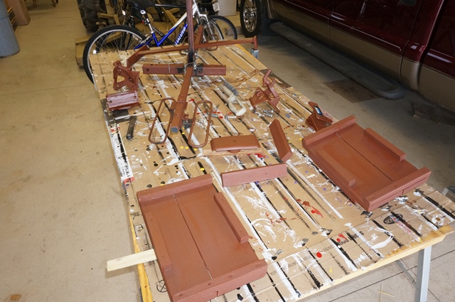
The right side outer frame rail and front steps. It is amazing at how much time it takes to paint steps.... 
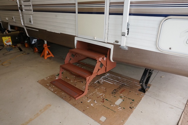
From the right side front axle area main frame rail to the A frame

The A Frame all painted. The parts are as well, just need to put it back together. The right side frame rail and steps still needs a black top coat.

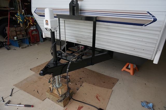
I have started from the right axles area to the end of the frame and started cutting and fitting the reinforcement steel to go on right side frame behind the rear axle hanger. This is also the last approx 15 feet of frame to scrape rust, prime and paint. And there is one more set of steps.... 

Spring is now in full growing season and house outside duties are calling my name... Plan is in the next week and a half or so, all the repairing for a while will be over.
All for now. Thanks for looking
John
__________________
Current Sunlines: 2004 T310SR, 2004 T1950, 2004 T2475, 2007 T2499, 2004 T317SR
Prior Sunlines: 2004 T2499 - Fern Blue
2005 Ford F350 Lariat, 6.8L V10 W/ 4.10 rear axle, CC, Short Bed, SRW. Reese HP trunnion bar hitch W/ HP DC
Google Custom Search For Sunline Owners Club
|
|
|
|
|
04-16-2017, 09:45 PM
|
#80
|
|
Moderator
Join Date: Dec 2006
Location: Michigan
Posts: 6,155
SUN #123
|
Looking good John! I can imagine your frame was much worse from all the miles you've put on it. Hopefully between the quality paint and primer, plus keeping it inside, you should get quite a few years out of it.
But it sure looks good when it's all done!
__________________
__________________
2007 T-286SR Cherry/Granola, #6236, original owner, current mileage: 9473.8 (as of 6/18/21)
1997 T-2653 Blue Denim, #5471
1979 12 1/2' MC, Beige & Avocado, #4639
Past Sunlines: '97 T-2653 #5089, '94 T-2251, '86 T-1550, '94 T-2363, '98 T-270SR
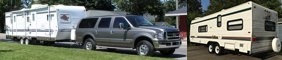
|
|
|
|
|
|
|
Currently Active Users Viewing This Thread: 1 (0 members and 1 guests)
|
|
|
 Posting Rules
|
You may not post new threads
You may not post replies
You may not post attachments
You may not edit your posts
HTML code is Off
|
|
|
|
 » Recent Sunline Discussions
 |
|
|
|
|
|
|
|
|
|
|
|
|
|
|
|
|
|
|
|
|
|
|
|


 Linear Mode

